High-pressure filtering station

A filter station, high-pressure technology, applied in filtration and separation, fixed filter element filters, multi-way valves, etc., can solve the problems of high-pressure liquid injection, installation and removal difficulties, tensile failure of connecting screws, etc., to reduce liquid flow resistance. , installation and removal of fast, large channel liquid flow effect

Active Publication Date: 2012-11-21
BEIJING TIANMA INTELLIGENT CONTROL TECH CO LTD
View PDF7 Cites 2 Cited by
  • Summary
  • Abstract
  • Description
  • Claims
  • Application Information

AI Technical Summary

Problems solved by technology

[0003] (1) The control valve is above the main body, and the control valve is easy to maintain, but the filter cartridge is under the main body, and it is difficult to replace the filter element, or there are also filter cartridges above the main body, which is convenient to replace the filter element, but the control valve is below, so it is difficult to maintain the control valve , especially the replacement of bulk spools is more difficult
[0004] (2) In the plate connection between the control valve and the main body, a rubber sealing ring is installed at the joint. If the seal fails, the high-pressure liquid will fill the entire joint surface, resulting in a large separation force between the control valve and the main body. A large tensile damage occurs, causing a large amount of high-pressure liquid to spray outward;
[0005] (3) The control valve assembly used is a bulk valve core, that is, a plurality of bulk valve core parts are loaded into the valve body in sequence. It is difficult to install and remove, and it takes a long time. Damage to seals;
[0006] (4) When the control liquid path of the main control valve is under pressure, the liquid inlet hole is connected to the filter cartridge and the filter element assembly, and the drain hole is disconnected from the filter cartridge and filter element assembly; when the control liquid path of the main control valve is depressurized, enter The liquid hole is disconnected from the filter cartridge and filter element assembly, and the drain hole is connected to the filter cartridge and filter element assembly, which achieves the purpose of labor-saving operation. However, it should be clearly pointed out that the main liquid supply pipe has pressure, and the control liquid circuit of the main control valve Controlled by the control valve, there can be pressure and pressure release; after the pump is stopped, the main liquid supply pipe has no pressure, and the control liquid path can only be without pressure. If the sewage hole is connected, it is connected to the atmosphere. When the working surface is higher than the filter station, the liquid in the main liquid supply pipeline will flow in vain, and the main liquid supply pipeline is long and thick, and there is not only a large amount of water in it, There are also very expensive emulsified oils, which cause a lot of waste

Method used


Image

  • High-pressure filtering station
  • High-pressure filtering station
  • High-pressure filtering station

Examples


Embodiment Construction

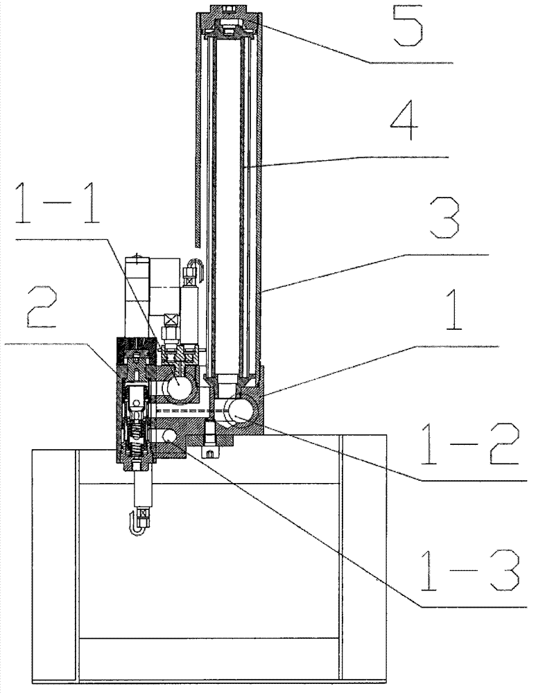
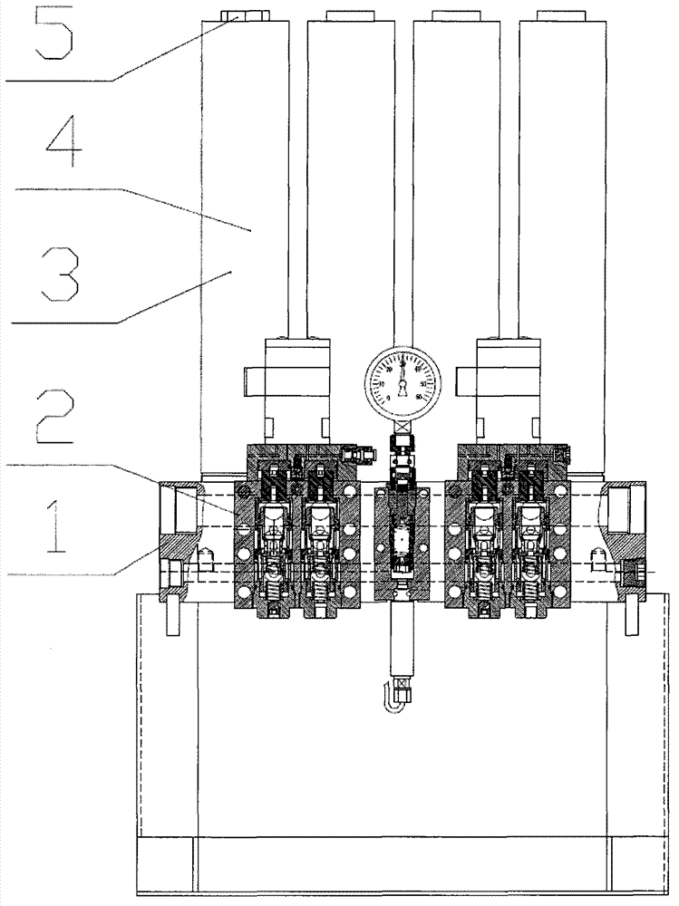
[0051] Such as figure 1 , figure 2 and Figure 5 As shown, the present invention includes a main body 1, a control valve 2 and a filter cartridge 3, and at least two filter cartridge installation holes 1-7 and filter element installation holes 1-8 are processed on the main body 1, and on one main body 1, namely A filter cartridge 3 is installed in each filter cartridge installation hole 1-7 at the upper end of the main body 1, a filter element 4 is installed in each filter cartridge 3 and in the filter element installation holes 1-8, and an upper filter element 4 is installed on the top of each filter element 4. The head 5 seals the top opening of the filter cartridge 3, and the control valve 2 is on the side of the main body 1, and the main body 1 is processed with a liquid inlet hole 1-1, a liquid outlet hole 1-2 and a sewage discharge hole 1-3;

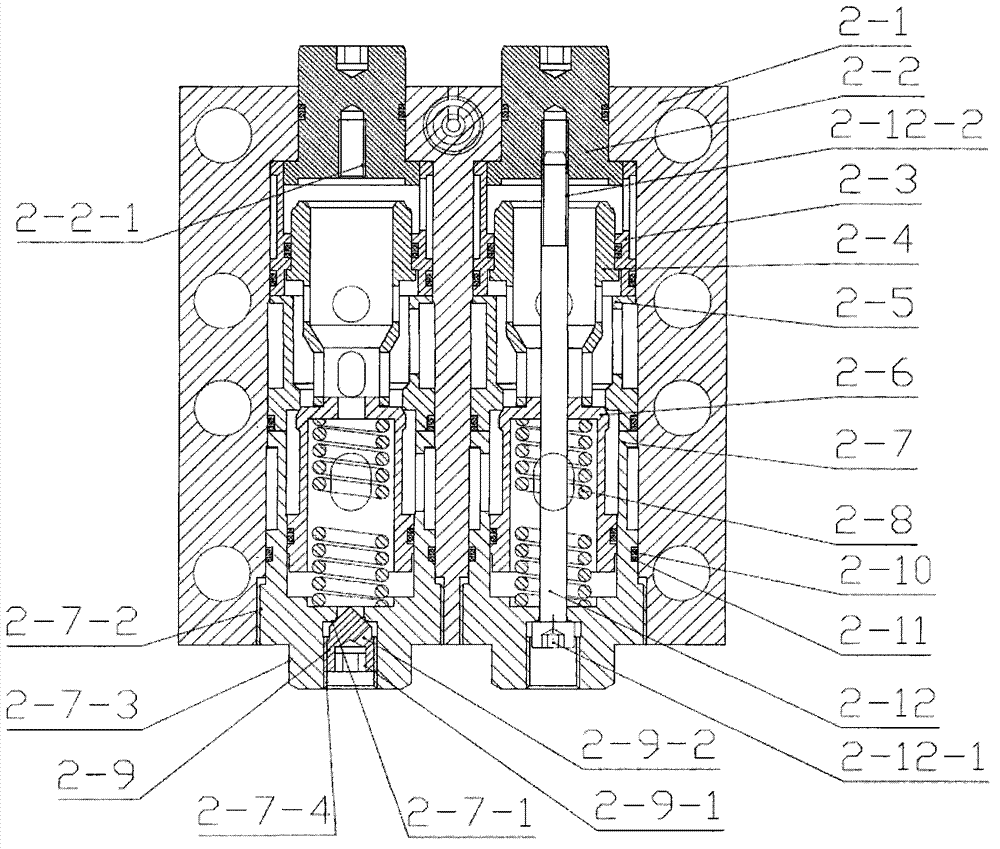
[0052] Such as image 3As shown, the control valve 2 adopted in the present invention includes a control valve body 2-1, and ...


PUM


Abstract

A high-pressure filtering station solves the problems that replacement of a filter element or maintenance of a control valve is difficult under a main body in a filter cartridge or the control valve of a traditional high-pressure filtering station and that high-pressure liquid is fully filled with a combined surface and jets outwards if the sealing between the control valve and the main body is failed. The high-pressure filtering station is characterized in that the filter cartridge is arranged above the main body; the control valve is arranged on the lateral surface of the main body; a liquid inlet trench though hole, a liquid outlet trench through hole, a sewage discharging trench through hole, an annular unloading groove and a linear unloading groove are formed in a valve body of the control valve by processing; a liquid inlet hole, a liquid outlet hole, a sewage discharging hole, a control valve liquid inlet trench through hole, a control valve liquid outlet trench through hole and a control valve sewage discharging trench through hole are formed in the main body by processing; and spare parts arranged in the valve body of the control valve can temporarily form an integrally-inserted valve core. The high-pressure filtering station has the beneficial effects that the replacement of the filter element or the maintenance of the control valve is easily realized; the phenomenon that a large amount of liquid is sprayed due to the fact that a sealing element is damaged is avoided; the liquid passes through a large channel; the flowing resistance of fluid is reduced; and the problem that the liquid in a main liquid supply pipeline flows outwards due to the fact that a work surface stops pumping is solved.

Description

technical field [0001] The invention belongs to a hydraulic filtering device, in particular to a high-pressure filtering station used for filtering industrial emulsions or clean water of coal mine hydraulic support, power generation, metallurgy and other industries. Background technique [0002] The high-pressure filtration station in the prior art is equipped with 2 filter cartridges and 2 filter elements on one main body. Multiple filter cartridges and multi-filter elements need to be combined through multiple units, which requires multiple thick pipeline connections. Complicated, bulky in structure and inconvenient to operate. In order to solve the above problems, the applicant filed an application number of 200810104350.7 in 2008, a notification number of CN101269281, and a patent named "Backwash High Pressure Filter Station". Inlet hole, liquid outlet hole and drain hole, more than 2 filter cartridges and more than 2 filter elements can be installed on the main body, a...

Claims


Application Information

Patent Timeline
IPC IPC(8): B01D29/11B01D29/52B01D29/66B01D29/60F16K11/14
Inventor 李继周
Owner BEIJING TIANMA INTELLIGENT CONTROL TECH CO LTD
Why Eureka
Try Eureka