Energy-saving emission-reducing energy comprehensive utilization system for construction

A technology for energy saving and emission reduction in buildings, applied in the direction of heating and cooling combination, machine operation mode, refrigerator, etc., can solve the problems of energy consumption, unfavorable outdoor environment, energy waste, etc., and achieve the effect of energy saving

Inactive Publication Date: 2012-11-21
苟仲武
View PDF5 Cites 60 Cited by
  • Summary
  • Abstract
  • Description
  • Claims
  • Application Information

AI Technical Summary

Problems solved by technology

However, after the air conditioner is turned on, although the indoor temperature is reduced, the heat is discharged to the outside, which is not conducive to the outdoor environment and causes energy waste
Another example is that household water heaters consume energy regardless of whether they use electric heating or gas, and fail to make good use of the heat energy emitted by air conditioners in summer, the heat energy emitted by the back panel of household refrigerators, and the energy emitted by kitchen exhaust ducts and range hoods.
Many home appliances need to emit heat, and some need to absorb heat to work. In addition, many heating devices, equipment, and machine resources are wasted and repeated.
For example, it is common for a family to have several air-conditioning outdoor units, resulting in waste of materials, metals and other materials, and also affecting the appearance of the city

Method used


Image

  • Energy-saving emission-reducing energy comprehensive utilization system for construction
  • Energy-saving emission-reducing energy comprehensive utilization system for construction

Examples


Embodiment Construction
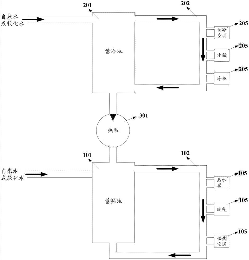
[0032] The main idea of ​​the present invention is to lay a heat source supply circulation pipeline dedicated to providing hot water in the building, so that various household equipment in the building (mainly heating household equipment such as heat exchange water heaters, floor heating systems, etc.) In the heating process, the heat source is used to supply the heat of the hot water in the circulation pipeline, so as to realize direct utilization of energy, comprehensive utilization, and reduction of conversion to save energy; and it is also possible to lay a cold source supply circulation pipeline dedicated to providing cold water, so that various buildings in the building Household equipment (mainly refrigerated household equipment such as refrigerators, freezers, waste heat recovery pipelines, etc.) can use cold sources to supply the cooling capacity of cold water in circulation pipelines during the refrigeration process to achieve heat recovery, reduce heat emissions, and ...


PUM


Abstract

The invention discloses an energy-saving emission-reducing energy comprehensive utilization system for a construction. The system comprises a heat storage tank, a heat source supply circulating pipeline and a heat supply device, wherein hot water in the heat storage tank flows into the heat source supply circulating pipeline through a water outlet of the heat storage tank and then flows back to the heat storage tank; the heat source supply circulating pipeline is paved in the construction and is connected to a room with a heat requirement in the construction; and the heat supply device is arranged in the room with the heat requirement and is in heat exchange contact with the hot water in the heat source supply circulating pipeline, so as to utilize the heat energy of the hot water in the heat source supply circulating pipeline during a heating process. The heat energy is directly outputted to each household device requiring for the heat energy through the hot water in the heat source supply circulating pipeline, the cold energy is outputted to each household device requiring for the cold energy through cold water in the heat source supply circulating pipeline, and the heat energy is recovered, so that the heat energy of various living environments in the construction is fully adjusted and recovered, and a large amount of energy resource consumption is greatly reduced.

Description

technical field [0001] The invention relates to energy saving and emission reduction technology, in particular to a comprehensive energy utilization system for energy saving and emission reduction in buildings. Background technique [0002] In recent years, with the development of the economy, the problems of energy saving and environmental protection have become more and more prominent. For example, in order to maintain indoor comfort in summer, many families and hotels generally turn on air conditioners to cool down the indoor temperature. However, after the air conditioner is turned on, although the indoor temperature is reduced, the heat is discharged outdoors, which is not conducive to the outdoor environment and causes energy waste. Another example is that household water heaters consume energy no matter whether they use electric heating or gas, and fail to make good use of the heat energy discharged by air conditioners in summer, the heat energy discharged from the b...

Claims


Application Information

Patent Timeline
Patent Type & Authority Applications(China)
IPC IPC(8): F25B29/00
Inventor 苟仲武
Owner 苟仲武
Why Eureka
Try Eureka