Image heating apparatus

一种加热装置、图像的技术,应用在滚筒加热装置、电热装置、欧姆电阻加热等方向,能够解决闪烁噪声和温度起伏导通期和控制循环困难等问题,达到抑制温度起伏的效果

Active Publication Date: 2012-11-21
CANON KK
View PDF8 Cites 7 Cited by
  • Summary
  • Abstract
  • Description
  • Claims
  • Application Information

AI Technical Summary

Problems solved by technology

[0011] Therefore, even with the configuration disclosed in Japanese Patent No. 3535529, both the requirements during heating up of the heater (reduction of overshoot) and the requirements during relatively stable periods such as the fixing period (reduction of flicker noise and temperature fluctuations) are satisfied The on-period and control loop become difficult

Method used


Image

  • Image heating apparatus
  • Image heating apparatus
  • Image heating apparatus

Examples


Embodiment 1

[0020] Hereinafter, Embodiment 1 of the present invention will be described with reference to the drawings.

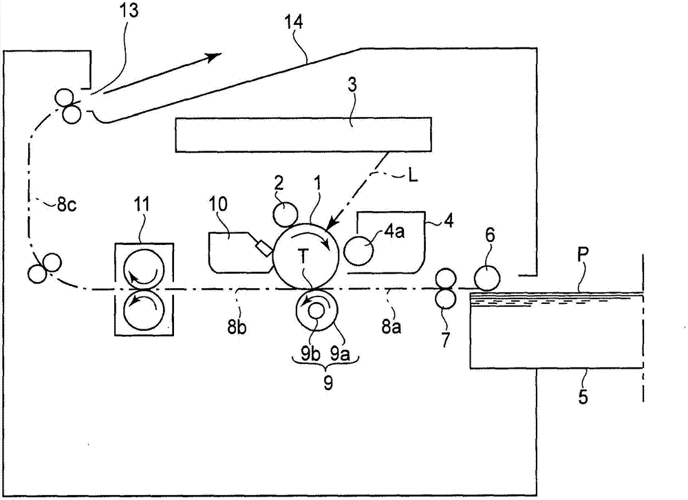
[0021] figure 2 is a schematic illustration of the imaging device according to the present embodiment. The image forming apparatus in this embodiment is an electrophotographic type laser beam printer. In the present embodiment, description will be made taking as an example a configuration in which the processing speed is about 200 m / s, the FPOT is about 6 seconds, and (when A4 size recording material is used) the throughput is about 33 ppm.

[0022] An electrophotographic photosensitive (member) drum 1 as an image bearing member is rotatably driven in a clockwise direction indicated by an arrow at a predetermined peripheral speed (process speed).

[0023] The contact charging roller 2 serving as charging means uniformly charges the surface of the photosensitive drum 1 to a predetermined polarity and a predetermined potential (main charging).

[0024] A laser beam s...

Embodiment 2

[0088] In this embodiment, basically the same configuration as in Embodiment 1 is employed. The differences are mainly described below.

[0089] There are various voltage values ​​for commercial power supplies depending on the country and region. For example, in the United Kingdom in Europe, the voltage value is 230V / 240V, in Germany, France, etc., it is 127V / 230V, in Asia, China, Korea, etc., it is 110V / 220V, in North America, the United States is 120V, and in Canada, it is 120V / 240V. Therefore, in some cases, imaging devices are narrowed down to imaging devices using an allowable voltage of 100V to 127V (machines supporting 100V) for the reason of obtaining commonality of imaging devices supplied to various countries to achieve cost reduction Two imaging devices consisting of an imaging device that uses an allowable voltage of 200 to 240V (machines that support 200V). In both the 100V-supporting machine and the 200V-supporting machine, the resistance value of the heater ...

Embodiment 3

[0111] This embodiment differs from Embodiment 1 in the following points.

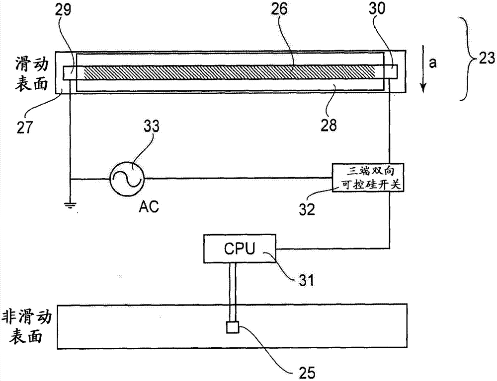
[0112] In Embodiment 1, the image number control in which the conduction period of the heater 23 is controlled by using one half-wave of the commercial power supply as the minimum unit is employed, and on the other hand in the present embodiment, the image number control is employed in the same manner as the commercial power supply in which the The phase angle in one half-wave of the power supply is controlled by a combination of phase controls of the type controlled.

[0113] Combined control of the image number control and phase control will be described later.

[0114] As described above, the image number control is such that either 100% energization or no energization (0% energization) is carried out with respect to one half-wave in a predetermined control cycle. On the other hand, the phase control makes it possible to control the conduction period in a predetermined control cycle at multiple lev...


PUM


Abstract

An image heating apparatus for heating a toner image in a nip while conveying a recording material on which the toner image is held is provided. The image heating apparatus includes a heater for generating heat by being supplied with electric power from an AC power source; a rotatable heating member for being heated by the heater; a pressing member for forming the nip in contact to the rotatable heating member; a temperature detecting portion for detecting a temperature of the heater or the rotatable heating member; and a controller for setting the electric power supplied to the heater every renewal cycle depending on a detected temperature by the temperature detecting portion. The renewal cycle is shorter in a rise period of the heater than in a period in which the recording material is conveyed in the nip.

Description

technical field [0001] The present invention relates to an image heating device. Background technique [0002] As a conventional image heating device of an electrophotographic type image forming device, a heated roller type image heating device is widely used. In the heat roller type image heating device, a recording material carrying an unfixed toner image thereon passes through a fixing nip formed by a fixing roller and a pressure roller rotating in pressing contact with each other, so that the toner image is fixed at on the record material. Also, in recent years, as an image heating device, an image heating device of a film heating type capable of achieving rapid temperature rise even when electric power consumption is suppressed during standby has been put into use. [0003] In these image heating apparatuses, when power supplied to the heater is controlled, it is necessary to control the heater so as not to cause excessive overshoot or undershoot of the temperature of...

Claims


Application Information

Patent Timeline
Patent Type & Authority Applications(China)
IPC IPC(8): G03G15/20H05B1/00
CPCH05B3/0095H05B1/00G03G15/205G03G15/20H05B3/141H05B2203/013
Inventor 中原久司山下贤太郎
Owner CANON KK
Why Eureka
Try Eureka