Control device for motor-driven vehicle

a technology for controlling devices and motor vehicles, which is applied in the direction of propulsion parts, propulsion using engine-driven generators, process and machine control, etc. it can solve problems such as performance problems, difficult to ensure electrical energy charging and discharging balance, and difficult control of energy balance, so as to achieve the effect of using lithium-ion batteries

Inactive Publication Date: 2009-10-27
HONDA MOTOR CO LTD
View PDF12 Cites 37 Cited by
  • Summary
  • Abstract
  • Description
  • Claims
  • Application Information

AI Technical Summary

Benefits of technology

[0010]Since the normal use zone is set in a predetermined range that includes a remaining capacity at which the discharge output according to the remaining capacity and the charge input according to the remaining capacity are equivalent, the discharge output and the charge input in the normal use zone can be set near the upper-limit value, and it is possible to use both as approximately equivalent values. Therefore, while ensuring the discharge output and the charge input are as large as possible, it is possible to readily ensure the balance of the discharge output and the charge input and possible to simultaneously achieve an increase in energy and fuel efficiency.
[0012]This constitution enables charging to be stopped in the state of the remaining capacity of the storage unit being restricted to some extent. Therefore, even when the storage unit is left as it is over an extended period under a high temperature, it is possible to reliably prevent performance changes that arise when the battery is thus left as it is over an extended period by holding the remaining capacity to a low capacity so that performance changes do not occur.
[0013]Also, when the temperature of the storage unit is lower than a predetermined temperature, the range of the normal use zone may be narrowed.
[0014]This constitution enables the temperature of the storage unit to be increased with discharge energy when performing control so that the storage unit, when in the charge zone, returns to the normal use zone by relatively increasing the charge zone that is set to the upper side of the normal use zone. Also, this constitution enables the temperature of the storage unit to be increased with charge energy when performing control so that the storage unit, when in the discharge zone, returns to the normal use zone by relatively increasing the discharge zone that is set to the lower side of the normal use zone. For this reason, it is possible to quickly warm the storage unit.
[0016]This constitution enables stopping discharging in the state of having ensured the remaining capacity of the storage unit to some extent. Therefore, there is the effect of being able to ensure a minimum output of the storage unit even during use under low temperatures where it is difficult to ensure output.
[0018]This constitution can make use of the characteristics of lithium-ion batteries, and so there is the effect of being able to effectively use a lithium-ion battery.

Problems solved by technology

However, when applied to a storage unit in which changes in the input / output upper limit are comparatively large with respect to the remaining capacity, as in a lithium-ion (Li-ion) battery, it is difficult to ensure that the charging and discharging of electrical energy is in balance.
As a result, control of the energy balance becomes difficult.
Also, particularly with a Li-ion battery, performance issues arise when the storage unit is left as it is over an extended period of time at a high temperature and with the remaining capacity on the overcharge side.

Method used


Image

  • Control device for motor-driven vehicle
  • Control device for motor-driven vehicle
  • Control device for motor-driven vehicle

Examples


Embodiment Construction

[0035]An embodiment of the present invention shall be described below with reference to the appended drawings.

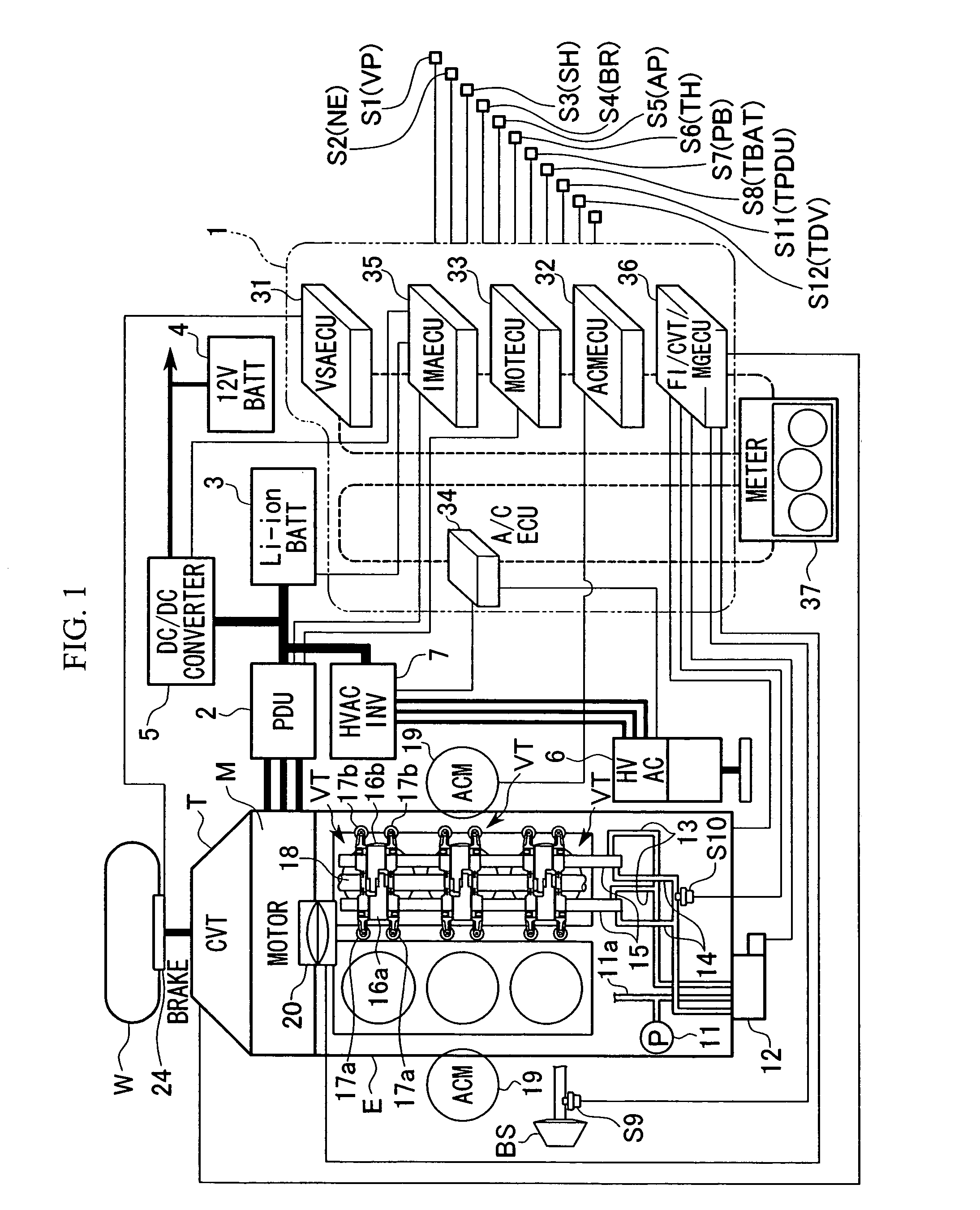
[0036]FIG. 1 shows a hybrid vehicle as one example of a motor-driven vehicle according to the embodiment of the present invention. The vehicle has a structure in which an internal-combustion engine (electricity generating device) E serving as a power source of the vehicle, an electric motor M serving as a power source, and a transmission T are coupled in series.

[0037]The driving force from both the engine (internal-combustion engine) E and the motor M are transmitted to left and right drive wheels W and W (front or rear) of the vehicle via a differential (not shown) that distributes the driving forces from the transmission T such as a continuously variable transmission (CVT) or a manual transmission (MT) to the drive wheels W and W. Furthermore, when a driving force is transmitted from the drive wheels W side to the motor M side during deceleration of the hybrid vehicle, the...


PUM


Abstract

A control device for a motor-driven vehicle, the control device includes: a zone determining unit that determines at least a normal use zone, a discharge zone, an over-discharge zone, a charge zone, and an over-charge zone; and a control unit controlling the motor by stipulating the charge and discharge power of the storage unit for each zone that is determined by the zone determining unit, setting the normal use zone to be in a predetermined range that includes a remaining capacity at which the discharge output according to the remaining capacity of the storage unit and the charge input according to the remaining capacity of the storage unit are equivalent, and making the discharge output and the charge input in the normal use zone to be a predetermined value regardless of the remaining capacity of the storage unit in the zone.

Description

BACKGROUND OF THE INVENTION[0001]1. Field of the Invention[0002]The present invention relates to a control device for a motor-driven vehicle such as a hybrid vehicle, an electric vehicle, and a fuel cell vehicle.[0003]Priority is claimed on Japanese Patent Application No. 2005-338467, filed Nov. 24, 2005, the content of which is incorporated herein by reference.[0004]2. Description of Related Art[0005]In a control device for a motor-driven vehicle such as a hybrid vehicle, a storage unit such as a battery is mounted as a drive unit of a motor for producing an assistance driving force to assist an engine or as a unit of recovering regenerative energy that is produced by regeneration by the motor. Since it is necessary to consider the remaining capacity of the storage unit when using it to drive the motor or using the motor as an electrical generator, a zone determining unit is provided that determines whether the remaining capacity of the storage unit is within a normal use zone, an ...

Claims


Application Information

Patent Timeline
Patent Type & Authority Patents(United States)
IPC IPC(8): B60L9/00B60L11/00E03B11/00F17D1/00H02J7/00H02J7/04H02J7/16B60K6/485B60K6/543B60L50/15B60W10/08B60W10/26B60W20/00
CPCB60K6/485B60K6/543B60W10/26B60W10/08Y02T10/6226B60W20/00Y10S903/917Y10T137/4757Y02T10/62B60W20/13B60W2510/246B60W2510/244
Inventor WAKASHIRO, TERUOSHIBUTANI, ATSUSHI
Owner HONDA MOTOR CO LTD
Why Eureka
Try Eureka