Liquid-cooled LED lighting device

a technology of led lighting and liquid cooling liquid, which is applied in the direction of lighting and heating equipment, process and machine control, instruments, etc., can solve the problems of thermal insulation, the efficiency of dissipation of the heat received by the cooling liquid to the outside air is significantly reduced, and the output power is limited

Inactive Publication Date: 2010-06-03
STANLEY ELECTRIC CO LTD
View PDF3 Cites 37 Cited by
  • Summary
  • Abstract
  • Description
  • Claims
  • Application Information

AI Technical Summary

Benefits of technology

[0045]Furthermore, in the liquid-cooled LED lighting device as configured above, even after the LED light source is turned off, the fan and the circulation pump of the liquid cooling system can remain activated for a period of time set by the timer circuit. Therefore, a temporal increase in the temperature of the tubing such as the rubber hoses and the circulation pump is prevented, and this ensures high reliability of the liquid-cooled LED lighting device.
[0046]In the liquid-cooled LED lighting device as configured above, when the temperature detected by the temperature detection element after the LED light source is turned off is or higher than a predetermined threshold value, the supply of the power to the liquid cooling system is maintained until the temperature detected by the temperature detection element is equal to or lower than the predetermined threshold value. Since the fan and the circulation pump remain energized during this period, the tubing such as the rubber hoses and the circulation pump can be cooled to a preset temperature in a reliable manner.
[0047]In the liquid-cooled LED lighting device as configured above, under cool conditions in which the temperature detected by the temperature detection element when the LED light source is turned on is lower than a predetermined threshold value, the power is not supplied to the liquid cooling system until the temperature detected by the temperature detection element is equal to or higher than the predetermined threshold value. Since cooling is not effected during this period, the entire liquid-cooled LED lighting device can be rapidly warmed to the required operating temperature.
[0048]In the liquid-cooled LED lighting device as configured above, the control unit can be provided with a temperature detection element, and can control the drive current for the LED light source based on a temperature detected by the temperature detection element. In this case, the LED drive current can be controlled within a range of from zero to a normal LED drive current. This control can suppress the excessive temperature increase when the LED light source is driven. As a result, the lighting device can utilize a higher power LED light source and ensure the stable illumination intensity and life as well as the high reliability of the device.
[0049]When the liquid-cooled LED lighting device is used in the area where a flammable gas with a certain flash point is present, the liquid-cooled LED lighting device can have a liquid cooling system disposed adjacent to the light source portion, including LEDs, and can control at least one of the LED light source-driving power supply and the liquid cooling system-driving power supply to maintain the temperature of the LED light source (the highest temperature of the LED light source at its emission portion) to be lower than the flash point of the flammable gas (for example, equal to or lower than 95° C.). Accordingly, even when the liquid-cooled LED lighting device of the presently disclosed subject matter is used in a dangerous area, it is possible to prevent possible explosion risks due to catching fire of the surrounding flammable gas.
[0050]The liquid-cooled LED lighting device of the presently disclosed subject matter utilizes as its light source an LED(s) that is substantially maintenance free. Accordingly, the replacement of light sources can be eliminated, thereby facilitating the maintenance thereof.
[0051]In the liquid-cooled LED lighting device as configured above, the temperature of any of the LED light source, the heat receiving jacket, and the metal base in contact with the heat receiving jacket is correctly detected by the thermistor or the temperature detection IC, and the liquid cooling system can thereby be appropriately controlled.
[0052]In the liquid-cooled LED lighting device as configured above, the liquid cooling system can remain energized for a predetermined time after the LED light source is turned off. Subsequently, when the supply of the power to the liquid cooling system is stopped and the liquid cooling system is stopped, the pilot lamp is turned on to indicate this condition. Therefore, a main power source switch can be switched off after the state of the pilot lamp is checked.
[0053]In the liquid-cooled LED lighting device as configured above, when the liquid cooling system, having operating portions such as a circulation pump and a fan, cannot work properly due to some accidents (namely, the cooling function is damaged), the control unit can control the current to be supplied to the LED light source to a value such that heat generated by the LED can be absorbed by the air cooling heat dissipation system. Accordingly, overheating of the LED can be prevented. In this case, although the illumination intensity may be lowered due to the suppressed current, the maximum temperature of the light source can be controlled to be lower than the flash point of the surrounding flammable gas. Thus, even when the liquid-cooled LED lighting device of the presently disclosed subject matter is used in a dangerous area, it is possible to prevent possible explosion risks.

Problems solved by technology

However, with the above natural cooling-heat dissipating structure, a high cooling effect is not expected, and, thus, there is a limit to the increase in the output power.
Therefore, the efficiency of dissipation of the heat received by the cooling liquid to the outside air is significantly reduced.
In addition, since the circulation of the cooling liquid is stopped, the flow of heat to the components connected to the heat receiving jacket and those in the downstream side are interrupted, and this results in thermal insulation.
This heat is transferred through the liquid in tubing, resulting in an increase in the temperature of other components such as the circulation pump and rubber hoses.
This causes a reduction in the reliability of the device.
This causes a problem in that the size of the reserve tank should be increased.
As described above, when the LED light sources are turned off and at the same time the liquid cooling system is stopped, the temperature of the circulation pump temporarily increases to about 100° C. This also causes a reduction in the reliability of the device.
As a result, the light conversion efficiency may deteriorate, and accordingly, the illumination intensity may also deteriorate.
In addition to the temperature change of ambient air, several causes that can lower the heat dissipation performance over time may be involved.
Accordingly, the liquid-cooling system is likely to be affected by temperature changes during operation of the LED as compared with heat dissipation caused by a heat dissipation structure utilizing an air cooling mechanism (such as a heat sink) with natural heat dissipation.
This system poses a problem in that a stable illumination intensity and life cannot be ensured.
Furthermore, if the circular pump and / or the fan do not properly operate due to unexpected external causes, breaking of the power supplying wire, and / or the expiration of its useful life, heat generated by the LEDs cannot be transferred from the heat receiving jacket to the downstream components.
In some worst cases, the temperature of cooling liquid may exceed its boiling point, which may cause the tubing to be broken, leading to liquid leakage.
However, it is difficult for a conventional lighting device that utilizes a discharge type light source lamp to completely prevent the occurrence of explosions caused by a lamp burst.
Accordingly, in order to lower the risk of explosion as much as possible, several explosion-protection structures have been developed, but these have not provided sufficient protection.
Furthermore, such a structure may require a thick glass member that has an increased strength for the discharge type light source lamp, and may employ complex connecting structures for components to enhance the hermeticity.
These structures may have a disadvantageously increased weight or volume caused by the used lamp.
Furthermore, since the discharge type light source lamp should be periodically replaced with a new one, there is a problem because maintenance, such as replacement of the lamp, may take a large amount of time and labor due to the complex structures, as described above.
In the liquid-cooled LED lighting device as configured above, when the liquid cooling system, having operating portions such as a circulation pump and a fan, cannot work properly due to some accidents (namely, the cooling function is damaged), the control unit can control the current to be supplied to the LED light source to a value such that heat generated by the LED can be absorbed by the air cooling heat dissipation system.

Method used


Image

  • Liquid-cooled LED lighting device
  • Liquid-cooled LED lighting device
  • Liquid-cooled LED lighting device

Examples


Embodiment Construction

[0090]A description will now be made below to liquid-cooled LED lighting devices according to the presently disclosed subject matter with reference to the accompanying drawings in accordance with exemplary embodiments. In the description of the subject application with reference to FIGS. 4 to 22, irrespective of the posture of the illustrated lighting device, the light emission direction may be referred to as “front (front surface side),” and the opposite direction may be referred to as “rear (rear surface side).”

[0091]First, the basic configuration of a liquid-cooled LED lighting device made in accordance with principles of the presently disclosed subject matter will be described with reference to FIGS. 4 to 7.

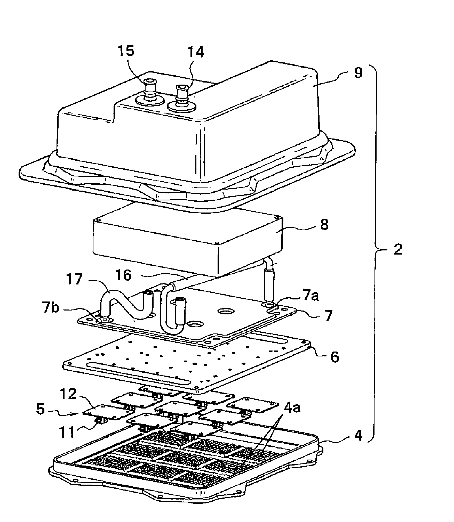
[0092]FIG. 4 is a perspective view illustrating the internal structure of the liquid-cooled LED lighting device according to the presently disclosed subject matter. FIG. 5 is an exploded perspective view of a device body of the liquid-cooled LED lighting device. FIG. 6 is a c...


PUM


Abstract

A liquid-cooled LED lighting device can be provided in which a temporal increase in the temperature of the tubing and the circulation pump when the LED light sources are turned off is prevented to ensure high reliability. The liquid-cooled LED lighting device can include an LED light source, a liquid cooling system including a heat receiving jacket and a radiator, an LED light source-driving power supply for supplying power to the LED light source, and a liquid cooling system-driving power supply for supplying power to the liquid cooling system. The LED lighting device can include a control unit, such as a timer circuit. The control unit can maintain supply of the power to the liquid cooling system for a predetermined period of time after supply of the power to the LED light source is stopped.

Description

[0001]This application claims the priority benefit under 35 U.S.C. §119 of Japanese Patent Applications No. 2008-299042 filed on Nov. 25, 2008, No. 2009-124948 filed on May 25, 2009, and No. 2009-125409 filed on May 25, 2009, which are hereby incorporated in their entirety by reference.TECHNICAL FIELD[0002]The presently disclosed subject matter relates to an LED lighting device. In particular, the presently disclosed subject matter relates to a liquid-cooled LED lighting device that employs a liquid-cooling system for cooling LED light sources.BACKGROUND ART[0003]In recent years, high intensity lamps, such as xenon lamps and sodium lamps, used as the light sources of lighting devices such as vehicle headlamps and exterior lighting devices are being replaced with semiconductor light emitting apparatuses (for example, such as LEDs) that have long life and low power consumption. Therefore, there is a demand for higher power LED lighting devices including LEDs as light sources.[0004]Mos...

Claims


Application Information

Patent Timeline
Patent Type & Authority Applications(United States)
IPC IPC(8): H01J13/32
CPCF21V15/01F21V19/001F21V25/12F21V31/005F21Y2101/02F21V29/30F21Y2115/10F21V29/00F21V29/57F21V29/67
Inventor YATSUDA, YASUSHIHIRAMOTO, YASUSHIYAMADA, MITSUOKOIKE, TERUO
Owner STANLEY ELECTRIC CO LTD
Why Eureka
Try Eureka