Image heating device and image forming apparatus using the same

a heating device and heating device technology, applied in the field of image heating device and image forming apparatus, can solve the problems of alteration or peeling of this elastic layer, and achieve the effects of short warm-up time, small capacity, and rapid heating

Inactive Publication Date: 2004-04-20
PANASONIC CORP
View PDF21 Cites 39 Cited by
  • Summary
  • Abstract
  • Description
  • Claims
  • Application Information

AI Technical Summary

Benefits of technology

The present invention has been made to overcome the above-mentioned problems of the prior art. It is an object of the present invention to provide an image heating device with a small capacity that can be heated rapidly and an image forming apparatus. It is a further object of the present invention to provide an image forming apparatus including an image heating device requiring a short warm-up time, which can deal with abnormal conditions and thus can be used stably.

Problems solved by technology

If the magnetization means heats the heat-generating member through magnetization before the rotating operation of the heat-generating member is started, a temperature of the heat-generating member is only partially made abnormally high, thereby causing alternation of the heat-resistant belt that is in contact with the heat-generating member, as well as permanent set of the belt in accordance with the curvature of the heat-generating member.
Further, if the surface of the belt is coated with an elastic layer made of silicone rubber, for example, a temperature of the belt is only partially made high, thereby causing alternation or peeling of this elastic layer.
In this case, however, since a temperature of the magnetization means is made high, there is a concern about a heat resistance of the magnetization means.

Method used


Image

  • Image heating device and image forming apparatus using the same
  • Image heating device and image forming apparatus using the same
  • Image heating device and image forming apparatus using the same

Examples


example 2

FIG. 5 is a cross-sectional view showing a fixing device serving as an image heating device in Example 2 of the present invention.

In this example, elements having the same structure and performing the same function as in the fixing device of Example 1 are referred to with the same numerals and their further explanation has been omitted.

A fixing belt 50 according to the present example is an endless belt of 60 mm diameter and 90 .mu.m thickness, which comprises a polyimide resin with a glass transition point of 320.degree. C. as a base 51. The surface of the fixing belt 50 is coated with silicone rubber 52 of 200 .mu.m thickness for fixing color images. Also in this example, the heat generation is performed with a heat-generating roller 54. Accordingly, a film-shaped heat-resistant resin such as a fluorocarbon resin can be used for the fixing belt 50.

The fixing belt 50 is suspended with a predetermined tensile force between a fixing roller 53 of 30 mm diameter, which is configured si...

example 3

FIG. 6 is a cross-sectional view showing a fixing device serving as an image heating device in Example 3 of the present invention.

In this example, elements having the same structure and performing the same function as in the fixing devices of Examples 1 and 2 are referred to with the same numerals and their further explanation has been omitted.

A fixing belt 90 shown in FIG. 6 is a belt comprising a belt base 91 fabricated by electroforming with nickel, which is 30 .mu.m in thickness and 60 mm in diameter, onto which silicone rubber 92 of 150 .mu.m thickness has been formed for fixing color images.

Between a heat-generating roller 54 and a fixing roller 53, an oil application roller 87 is provided so as to be in contact with the outer peripheral surface of the fixing belt 90. Further, a temperature sensor 58 is provided in opposition to the oil application roller 87 so as to be in contact with the inner peripheral surface of the fixing belt 90. The detected output from the temperature...

example 4

FIG. 7 is a cross-sectional view showing a fixing device serving as an image heating device in Example 4 of the present invention, FIG. 8 is a plan view showing the fixing device in FIG. 7 as viewed in the arrow direction A, FIG. 9 is a cross-sectional view showing the fixing device in FIG. 7 taken along the center line.

In FIGS. 7 to 9, reference numeral 21a denotes a fixed semicylindrical heat generating member and reference numeral 25 denotes a magnetization coil. The magnetization coil 25 is formed of bundled wires comprising 40 copper wires of 0.15 mm diameter with insulated surfaces. The bundled wire extends in the longitudinal direction of a heat-generating member 21a (i.e., perpendicular to the face of FIG. 7) while winding around the heat-generating roller 21a in its circumferential direction.

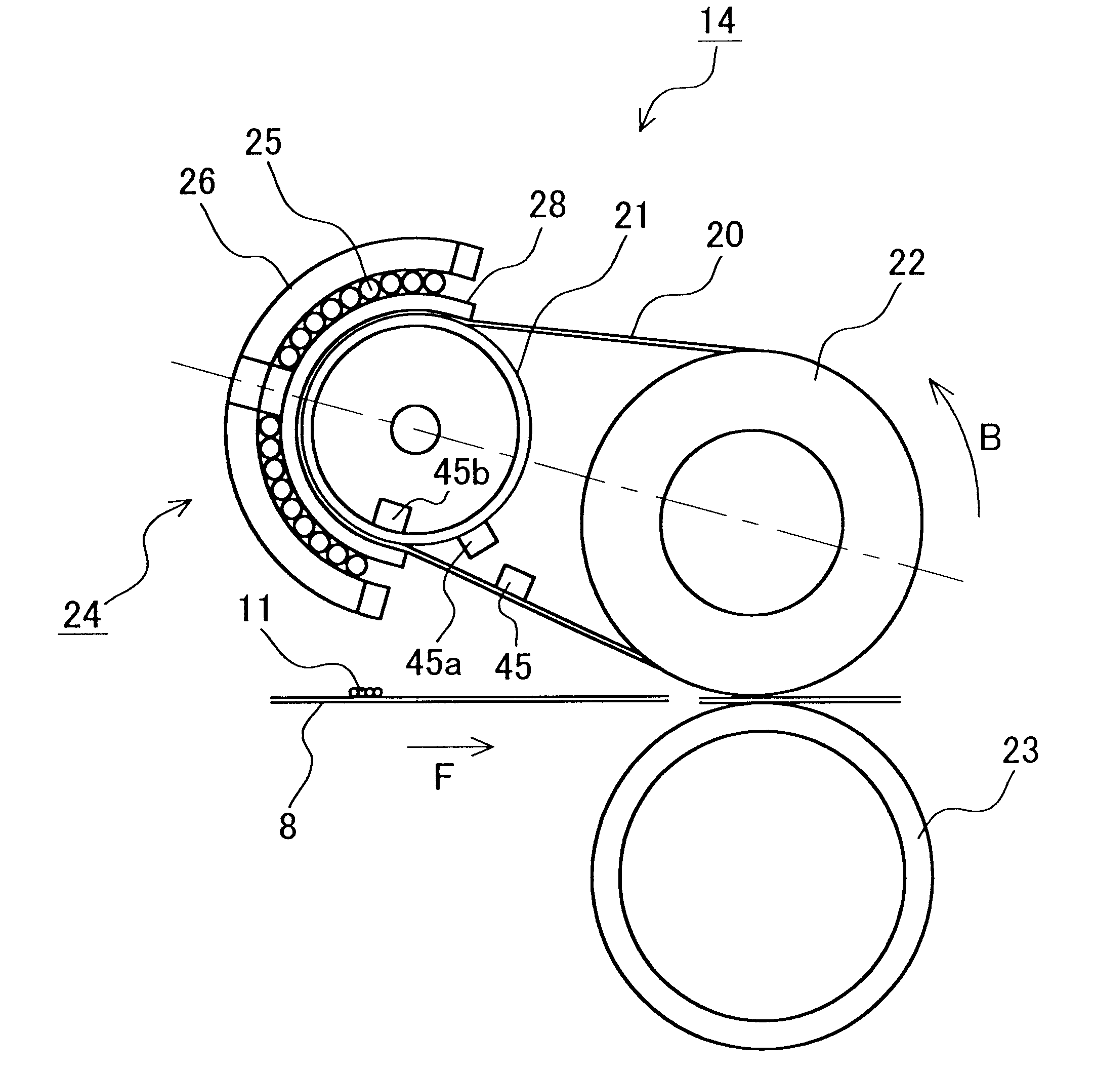
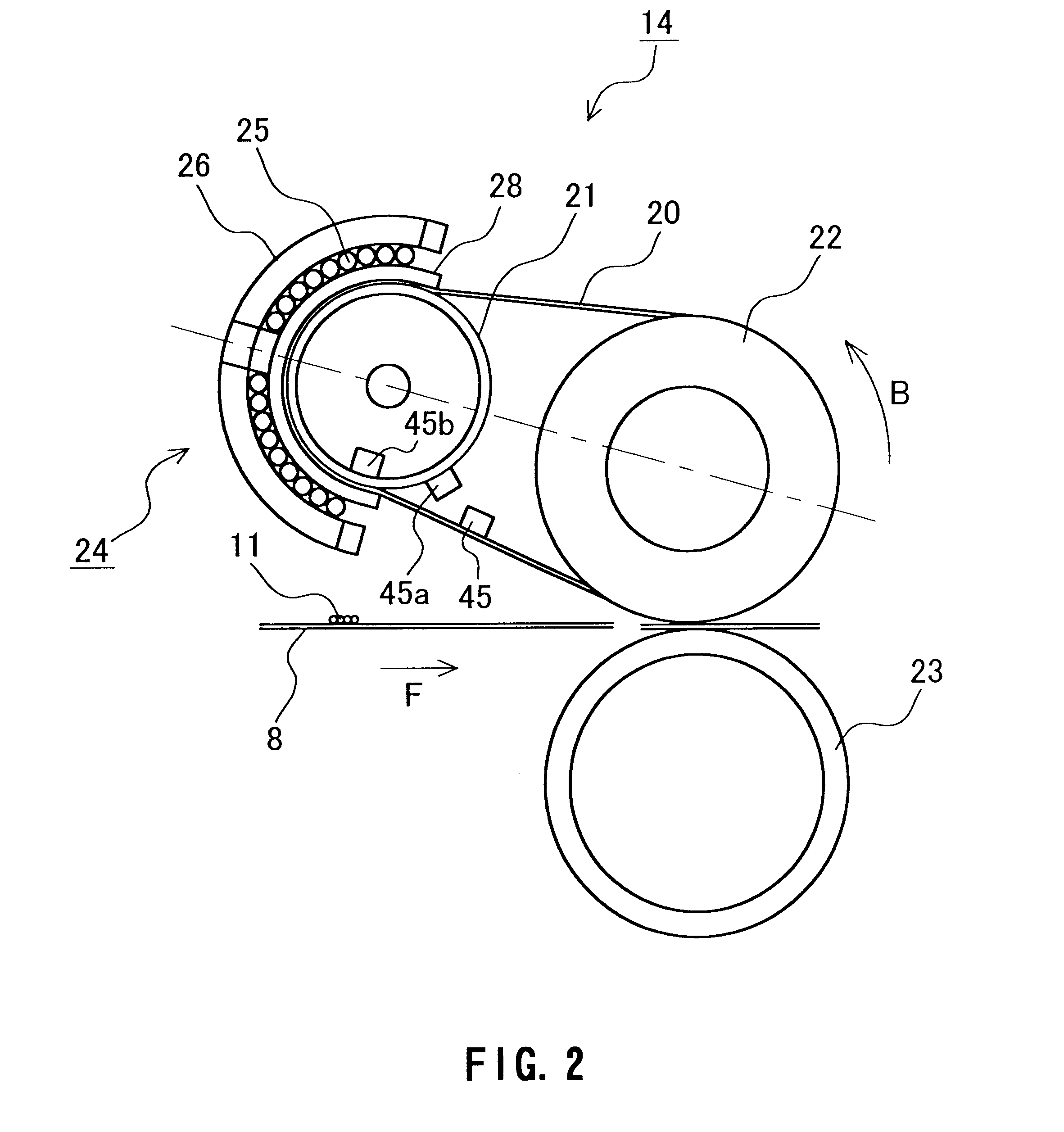
The cross section of the magnetization coil 25 perpendicular to the longitudinal direction of the heat-generating member 21a is formed so as to cover a fixing belt 20 looped around the ...


PUM


Abstract

An image heating device with a small thermal capacity that can be heated rapidly. The image heating device includes a fixing belt (20) having a heat resistance; a rotatable heat-generating roller (21), which is at least partially conductive and arranged in contact with an inner peripheral surface of the fixing belt (20); a fixing roller (22), the fixing roller and the heat-generating roller (21) movably suspending the fixing belt (20) therebetween; and a magnetization means (24) for heating the heat-generating roller (21) through magnetization, which is arranged outside the heat-generating roller (21). In this image heating device, the magnetization means (24) heats the heat-generating roller (21) through magnetization after a rotating operation of the heat-generating roller (21) is started.

Description

The present invention relates to an image heating device permitting reduction of warm-up time and an image forming apparatus. More particularly, the present invention relates to an image heating device for use in image forming apparatus, such as electrophotographical apparatus or electrostatic recording apparatus, that is suitable as a fixing device for fixing unfixed images, and to an image forming apparatus.Conventionally, as image heating devices, for which fixing devices are a typical example, contact-heating devices such as heat roller type devices and belt type devices, generally have been used.In recent years, due to the demand for shorter warm-up time and reduced energy consumption, electromagnetic induction heating, by which rapid heating and high efficiency heating are likely to be attained, are attracting great attention (see JP 10(1998)-123861 A).FIG. 23 shows a cross-sectional view of an image heating device utilizing the electromagnetic induction, which is disclosed in...

Claims


Application Information

Patent Timeline
Patent Type & Authority Patents(United States)
IPC IPC(8): G03G15/20
CPCG03G15/2064G03G15/2025G03G15/2028G03G2215/2016G03G2215/2025G03G2215/2032
Inventor TATEMATSU, HIDEKIASAKURA, KENJIIMAI, MASARU
Owner PANASONIC CORP
Why Eureka
Try Eureka