Method for producing resin molded article, resin molded article, resin molded article for endoscope, endoscope using resin molded article, and apparatus for producing the resin molded article
A resin molding and manufacturing method technology, applied in the field of manufacturing equipment for resin molded products, capable of solving problems such as adverse effects of optical components on optical functions
- Summary
- Abstract
- Description
- Claims
- Application Information
AI Technical Summary
Problems solved by technology
Method used
Image
Examples
no. 1 Embodiment approach
[0056] (structure)
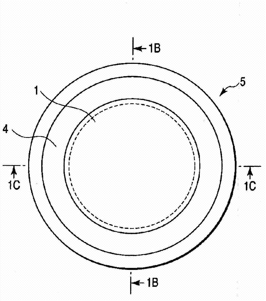
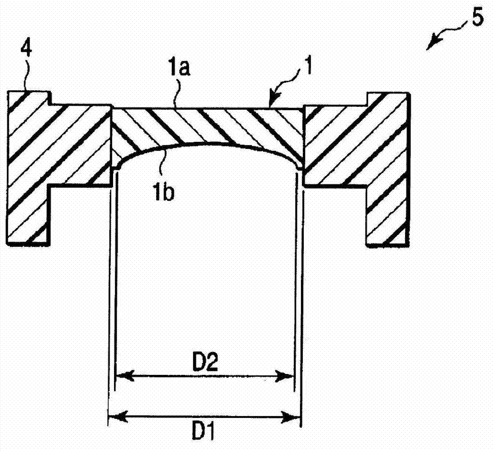
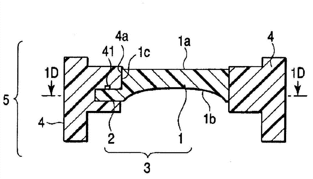
[0057] Figure 1A , Figure 1B , Figure 1C , Figure 1D , 19 d27edc-bf6d-4590-b119-9a5170c7637e shows the first embodiment of the present invention. Figure 1A It is a plan view of a two-color molded product 5 which is a resin molded product of the present embodiment. Figure 1B yes Figure 1A The 1B-1B line profile, Figure 1C yes Figure 1A The 1C-1C line profile, Figure 1D yes Figure 1C 1D-1D line profile. and, figure 2 It is an overall vertical cross-sectional view of a two-color molding die (molding die) 28 for molding the two-color molded product 5 .
[0058] Such as Figure 1A , Figure 1B , Figure 1C , Figure 1D As shown, the two-color molded product 5 includes: a primary molded body 3 having an optical element 1 and a protruding portion 2 protruding from the outer periphery of the optical element 1, and a cylindrical support member (secondary molded body) that supports the optical element 1. ) 4. The optical element 1 is formed ...
no. 2 Embodiment approach
[0101] (structure)
[0102] Figure 20 and Figure 21 The second embodiment of the present invention is shown. In the first embodiment, one protrusion 2 is provided on a part of the outer peripheral surface of the optical element 1 of the primary molded body 3 . In this embodiment, two protrusions 2a, 2b are provided on the outer peripheral surface of the optical element 1 of the primary molded body 3 . The two protrusions 2 a and 2 b are arranged so as to be separated from each other by 180° in the circumferential direction of the optical element 1 . Furthermore, each of the two protruding parts 2a and 2b has a width sufficient to provide a pin gate 24a required for molding the primary molded body 3 . In addition, the two protrusions 2a and 2b may have the same size or different sizes.
[0103] With respect to the thickness direction of the optical element 1 , the thickness of the two protruding portions 2 a and 2 b is smaller than the thickness of the portion adjacent t...
no. 3 Embodiment approach
[0114] (structure)
[0115] Figure 24 , Figure 25A , Figure 25B , Figure 26 , Figure 27 , Figure 28 , Figure 29 The third embodiment of the present invention is shown. In this embodiment, the present invention is applied to the distal end portion 306 of the endoscope 301 . Figure 24 The overall configuration of an endoscope 301 for observing the inside of a body cavity and performing diagnosis, treatment, etc. is shown. The endoscope 301 has an elongated and flexible insertion portion 305 to be inserted into a patient's body cavity. A rigid distal end portion 306 is provided at the distal end of the insertion portion 305 , and an operation portion 307 is provided at the proximal end of the insertion portion 305 .
[0116] The insertion portion 305 has an elongated flexible tube portion 305a and a bent portion 305b connected to the distal end of the flexible tube portion 305a. The front-end part 306 is connected to the front-end|tip of this bending part 305b. ...
PUM
 Abstract
Description
Claims
Application Information
 - R&D
- Intellectual Property
- Life Sciences
- Materials
- Tech Scout
- Unparalleled Data Quality
- Higher Quality Content
- 60% Fewer Hallucinations
Browse by: Latest US Patents, China's latest patents, Technical Efficacy Thesaurus, Application Domain, Technology Topic, Popular Technical Reports.
© 2025 PatSnap. All rights reserved.Legal|Privacy policy|Modern Slavery Act Transparency Statement|Sitemap|About US| Contact US: help@patsnap.com


