
Sand box positioning device

A technology of positioning device and positioning position, which is applied in the direction of mold box, casting equipment, metal processing equipment, etc., can solve the problems of high labor cost, unsuitable core setting accuracy, high manufacturing cost and management cost, etc., to ensure repeatability. The effect of positioning accuracy, high-precision positioning of the sandbox, and simplified fixture tooling

Active Publication Date: 2014-06-04
GUANGXI YUCHAI MASCH CO LTD
View PDF5 Cites 0 Cited by
  • Summary
  • Abstract
  • Description
  • Claims
  • Application Information

AI Technical Summary

Problems solved by technology

[0002] At present, in the foundry industry at home and abroad, there is no molding production line using robot core technology. The core setting methods adopted by most domestic and foreign enterprises include: first, manual handling and direct core setting; second, manual handling to the core mould. First, the manipulator clamps the sand core to lower the core; third, manually transports to the core assembly mold to control the simple spreader to clamp the sand core to the lower core
[0003] The main problem of the above-mentioned core setting method is that it is difficult to solve the precise positioning of the sand core and the sand box, and the core setting cannot guarantee the repeat positioning accuracy
[0004] At the same time, manipulators and simple fixtures are inflexible when using jigs and cored tires, and the versatility of fixtures and cored tires is poor. Changes in castings require redesign and manufacture, resulting in high manufacturing and management costs; manual handling and direct core placement can only be used for small sand cores. Moreover, the accuracy of core setting is not suitable to be guaranteed, the human influence is large, and the labor cost is high at the same time. The core setting process requires at least 3 to 5 operators.

Method used


Image

  • Sand box positioning device
  • Sand box positioning device
  • Sand box positioning device

Examples


Embodiment Construction

[0020] A specific embodiment of the present invention will be described in detail below in conjunction with the accompanying drawings, but it should be understood that the protection scope of the present invention is not limited by the specific embodiment.

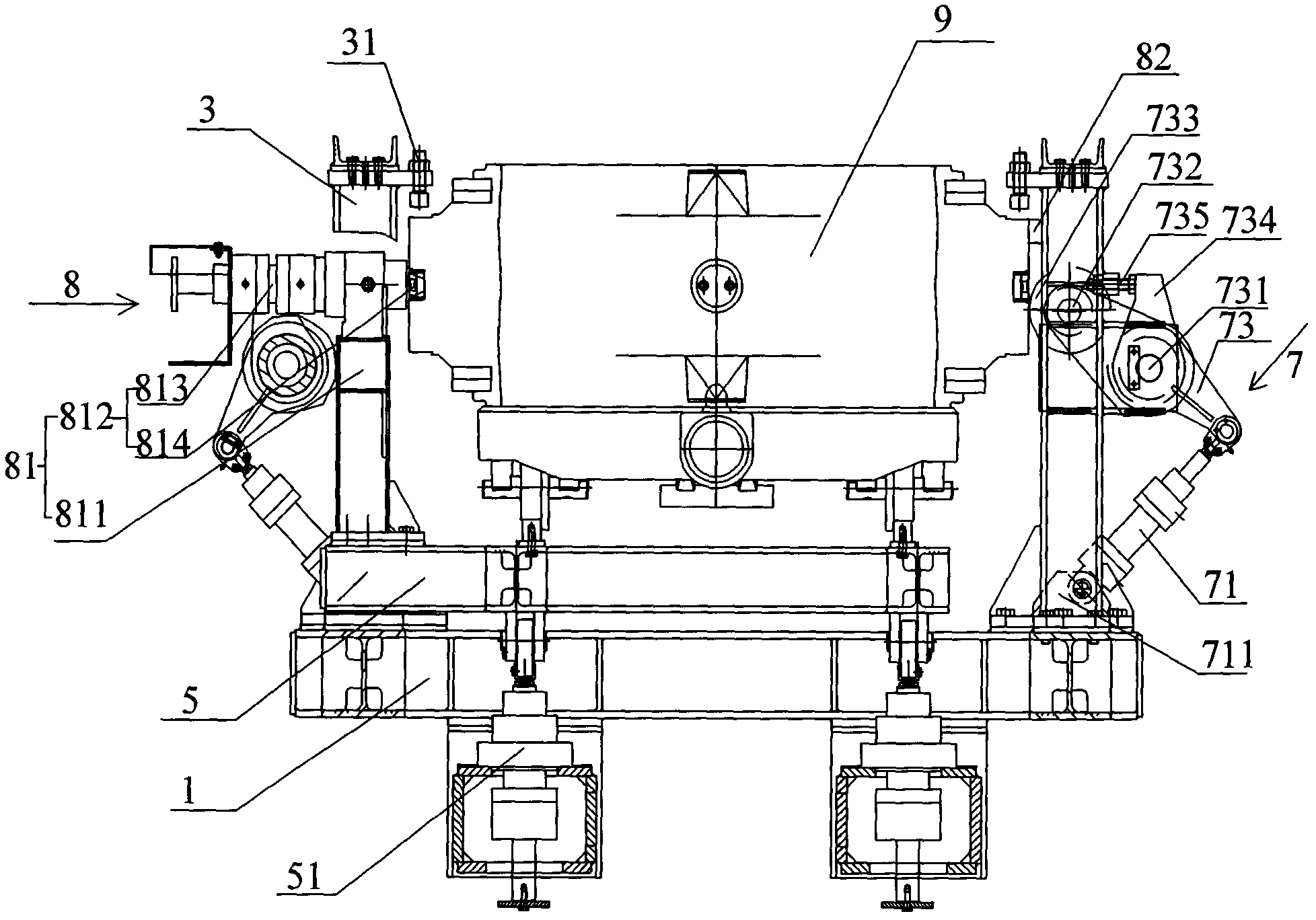
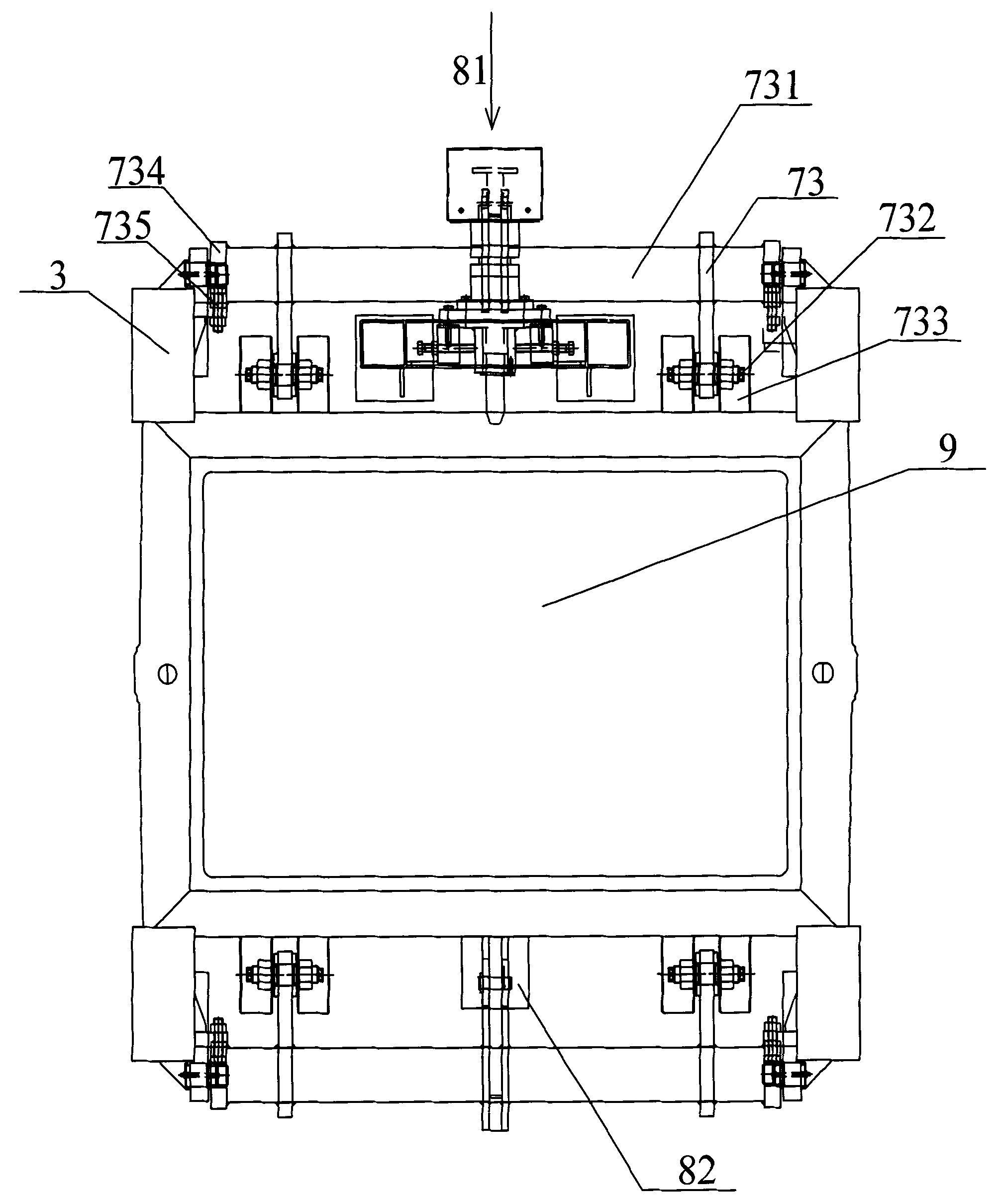
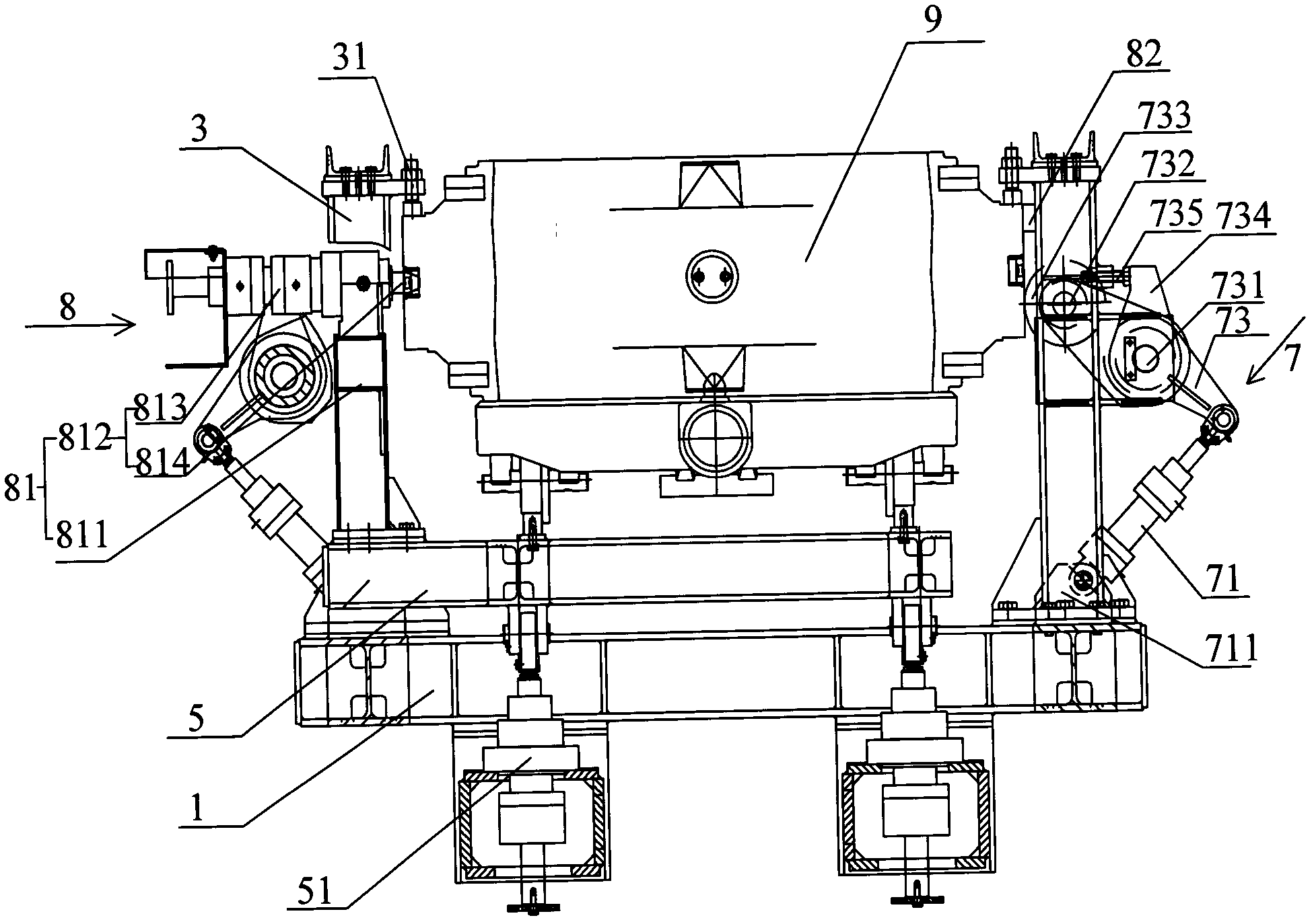
[0021] figure 1 , figure 2 and image 3 A preferred embodiment of the invention is shown (with figure 1 The left and right direction in is horizontal, perpendicular to figure 1 Orientation on paper is portrait). see figure 1 , the sand box positioning device includes: an underframe 1 and vertical stands 3 fixed on both lateral sides of the underframe 1, the underframe 1 is provided with a sand box push-up plate 5 and a pair of eccentric wheel lateral positioning components 7, and the sand box The box push-up plate 5 is connected with the first driving mechanism 51 (which may be a hydraulic cylinder), and has a positioning position and a leveling position for moving up and down (that is, figure 1 In the up and down d...


PUM


Abstract

The invention discloses a sand box positioning device. The sand box positioning device comprises a bottom frame (1) and vertical frames (3) which are fixed on two sides of the bottom frame (1) in a horizontal direction; the bottom frame (1) is provided with a sand box pushing plate (5) and eccentric wheel horizontal positioning assemblies (7) which are in pair; the sand box pushing plate (5) is connected with first drive mechanisms (51) and is provided with a positioning device and a leveling device which can move up and down, and a longitudinal positioning assembly (8); and the tops of the vertical frames (3) are provided with leveling parts (31). According to the sand box positioning device, a plurality of positioning mechanisms are used for positioning a sand box, and a plurality of leveling mechanisms are used for leveling the sand box, so that the defect of low sand box positioning accuracy in the prior art can be overcome further, the effect of positioning the sand box accurately can be achieved, and the repeated positioning accuracy of core setting can be guaranteed further; and therefore, clamps and fixtures of robots or mechanical arms can be simplified, a core can be set fully-automatically, a casting is high in dimensional accuracy, the core setting cost is saved, and production efficiency can be improved.

Description

technical field [0001] The invention relates to the field of casting, in particular to a sand box positioning device. Background technique [0002] At present, in the foundry industry at home and abroad, there is no molding production line using robot core technology. The core setting methods adopted by most domestic and foreign enterprises include: first, manual handling and direct core setting; second, manual handling to the core mould. First, the manipulator clamps the lower core of the sand core; third, it is manually transported to the core assembly mold to control the simple spreader to clamp the lower core of the sand core. [0003] The main problem of the above-mentioned core setting method is that it is difficult to solve the precise positioning of the sand core and the sand box, and the core setting cannot guarantee the repeated positioning accuracy. [0004] At the same time, manipulators and simple fixtures are inflexible when using jigs and cored tires, and the...

Claims


Application Information

Patent Timeline
Patent Type & Authority Patents(China)
IPC IPC(8): B22C21/00
Inventor 杨双华邓宗钰陈祖礼黎武新廖文东刘毅
Owner GUANGXI YUCHAI MASCH CO LTD
Learn More