Potential energy converting device of novel hydraulic piston pump

A technology of hydraulic piston and conversion device, which is applied to piston pump, pump, liquid variable capacity machinery, etc., can solve the problems of long construction period, high cost and high cost, and achieve the effect of simple and practical structure and reasonable design.

Inactive Publication Date: 2012-11-28
温锡钦
View PDF6 Cites 13 Cited by
  • Summary
  • Abstract
  • Description
  • Claims
  • Application Information

AI Technical Summary

Problems solved by technology

Humans can use the gravitational potential energy of nature to do energy conversion, such as hydroelectric generators. However, using hydroelectric generators to generate electricity is not only greatly affected by climate change, but also more restricted by geographical location. Therefore, hydroelectric generator stations can only It is established in a small number of special areas, and the construction period is long, the cost is high, and it will have a certain adverse impact on the geographical environment after completion, and the generated electricity still needs high costs during transmission

Method used


Image

  • Potential energy converting device of novel hydraulic piston pump
  • Potential energy converting device of novel hydraulic piston pump
  • Potential energy converting device of novel hydraulic piston pump

Examples


Embodiment approach 1

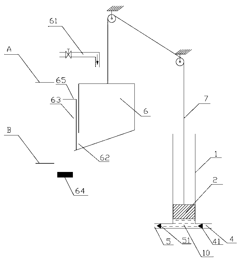
[0029] Implementation mode one: if figure 1 As shown, the potential energy conversion device of the novel hydraulic piston pump includes a piston pump mechanism. The piston pump mechanism includes a cylinder body 1 and a piston 2. The cylinder body 1 is provided with a fluid feed pipe 4 and a fluid discharge pipe 5, and the fluid feed pipe 4 and the fluid discharge pipe 5 are all provided with check valves. Among the cylinder body 1 and the piston 2, one is fixed and is a fixed piston part, and the other moves linearly and reciprocatingly and is a movable piston part. It is characterized in that: It also includes a gravity water container 6 and a reset device, wherein the gravity water container 6 is connected with the movable piston part by a stay rope 7, a water injection pipe 61 and a valve are arranged above the gravity water container 6, and a water outlet 62 is opened on the gravity water container 6 , and is provided with a gate 63, and is equipped with a gate trigger ...

Embodiment approach 2

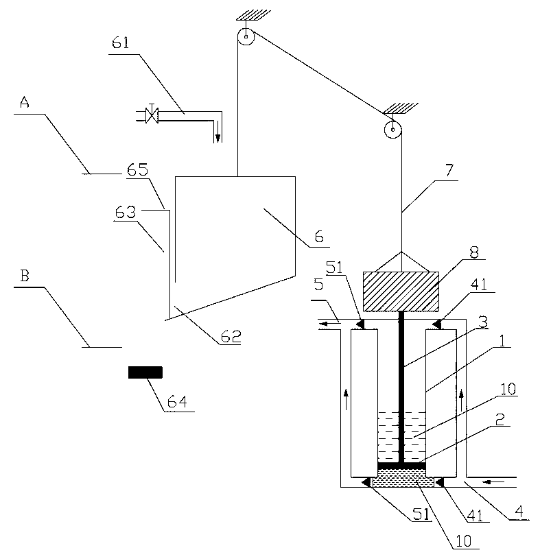
[0034] Implementation mode two: if figure 2As shown: the potential energy conversion device of the new hydraulic piston pump includes a piston pump mechanism, the piston pump mechanism includes a cylinder body 1 and a piston 2, the cylinder body 1 is provided with a fluid feed pipe 4 and a fluid discharge pipe 5, and the fluid feed pipe 4 and the fluid discharge pipe 5 are all provided with check valves. Among the cylinder body 1 and the piston 2, one is fixed and is a fixed piston part, and the other moves linearly and reciprocatingly and is a movable piston part. It is characterized in that: It also includes a gravity water container 6 and a reset device, wherein the gravity water container 6 is connected with the movable piston part by a stay cord 7 and a connecting rod 3, the top of the gravity water container 6 is provided with a water injection pipe 61 and a valve, and the gravity water container 6 is opened. There is a water outlet 62, a gate 63, and a trigger device f...

Embodiment approach 3

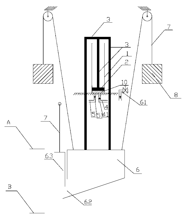
[0040] Implementation mode three: if image 3 As shown, the potential energy conversion device of the novel hydraulic piston pump includes a piston pump mechanism. The piston pump mechanism includes a cylinder body 1 and a piston 2. The cylinder body 1 is provided with a fluid feed pipe 4 and a fluid discharge pipe 5, and the fluid feed pipe 4 and the fluid discharge pipe 5 are all provided with check valves. Among the cylinder body 1 and the piston 2, one is fixed and is a fixed piston part, and the other moves linearly and reciprocatingly and is a movable piston part. It is characterized in that: It also includes a gravity water container 6 and a reset device, wherein the gravity water container 6 and the movable piston are connected by a connecting rod 3, a water injection pipe 61 and a valve are arranged above the gravity water container 6, and a water outlet 62 is opened on the gravity water container 6 , and is provided with a gate 63, and is equipped with a gate trigger...


PUM


Abstract

The invention relates to a potential energy converting device of a novel hydraulic piston pump. Most conventional piston pumps are driven by motors or diesel engines and have deficiencies of needing to use electricity, diesel, and the like. Therefore, the potential energy converting device comprises a piston pump mechanism, wherein the piston pump mechanism comprises a cylinder body and a piston; a fluid material inlet pipe and a fluid material outlet pipe are arranged on the cylinder body; and check valves are arranged on both the fluid material inlet pipe and the fluid material outlet pipe. The potential energy converting device is characterized in that the potential energy converting device further comprises a gravity water container and a resetting device, wherein the gravity water container is connected with the piston through a pull rope or/and a connecting rod; a water filling pipe and a valve are arranged above the gravity water container; a water outlet and a sluice gate are arranged on the gravity water container; and a sluice gate triggering device is arranged on the gravity water container in a matched manner. The potential energy converting device of the novel hydraulic piston pump, which is disclosed by the invention, has the advantages of reasonable design and simple and practical structure, and utilizes the gravity or buoyancy force of water with a certain water level difference to do work to increase the pressure intensity of fluid, thereby achieving the aims of water lifting, refrigeration, heating, power generation, and the like and serving the humankind.

Description

technical field [0001] The invention relates to a potential energy conversion device of a piston pump, in particular to a novel hydraulic piston pump potential energy conversion device. Background technique [0002] Existing piston pumps, such as rotary piston pumps and reciprocating piston pumps, are mostly driven by motors or diesel engines, which have the disadvantages of needing electricity and oil, and are rarely driven by gravity or buoyancy. In such cases, gravity or buoyancy is a natural source of drive. Humans can use the gravitational potential energy of nature to do energy conversion, such as hydroelectric generators. However, using hydroelectric generators to generate electricity is not only greatly affected by climate change, but also more restricted by geographical location. Therefore, hydroelectric generator stations can only It is established in a small number of special areas, and the construction period is long, the cost is high, and there will be certain ...

Claims


Application Information

Patent Timeline
Patent Type & Authority Applications(China)
IPC IPC(8): F03G3/00F04B9/10
Inventor 温锡钦温锡金万城朱贞键朱不妹温武佳温武銮郑明练郑明坤
Owner 温锡钦
Why Eureka
Try Eureka