
Piston with sealing piece

A technology of seals and pistons, which is applied in the field of pistons, can solve the problems of flowing into the upper part of the piston cylinder, polluting the working environment, hydraulic oil loss, etc., and achieves the effects of reducing loss, saving hydraulic energy, and tight sliding fit

Inactive Publication Date: 2012-11-28
范跃卫
View PDF5 Cites 4 Cited by
  • Summary
  • Abstract
  • Description
  • Claims
  • Application Information

AI Technical Summary

Problems solved by technology

[0002] When the piston moves in the piston cylinder, the gap between the piston and the piston cylinder wall is generally sealed by an O-ring, but for some working conditions with high sealing requirements, such as in the piston cylinder, high-pressure oil is passed under the piston, while A spring is connected to the top of the piston, and the piston returns through the spring. If an ordinary sealing ring is used, high-pressure oil will easily flow into the upper part of the piston cylinder from the gap between the piston cylinder and the piston, causing loss of hydraulic oil and polluting the working environment. The gap between the sealing ring and the cylinder wall of the piston cylinder is set very small, although it can reduce the flow of high-pressure oil into the upper part of the piston cylinder from the gap between the piston cylinder and the piston, but due to the friction between the sealing ring and the cylinder wall of the piston cylinder When the piston increases, a larger spring is required to overcome the frictional force to make the piston return. When the piston needs to move upward, a greater hydraulic pressure is required to overcome the elastic force of the spring and the friction between the seal ring and the cylinder wall of the piston cylinder. Friction, causing waste of hydraulic energy

Method used


Image

  • Piston with sealing piece
  • Piston with sealing piece
  • Piston with sealing piece

Examples


Embodiment Construction

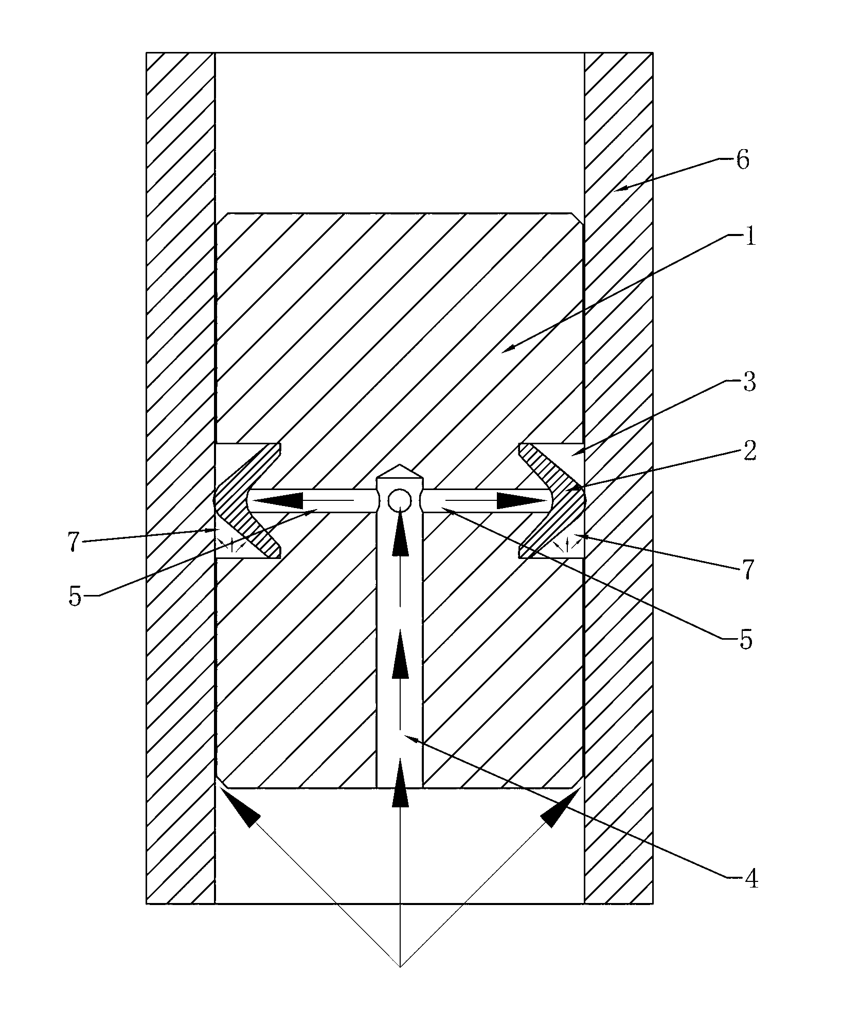
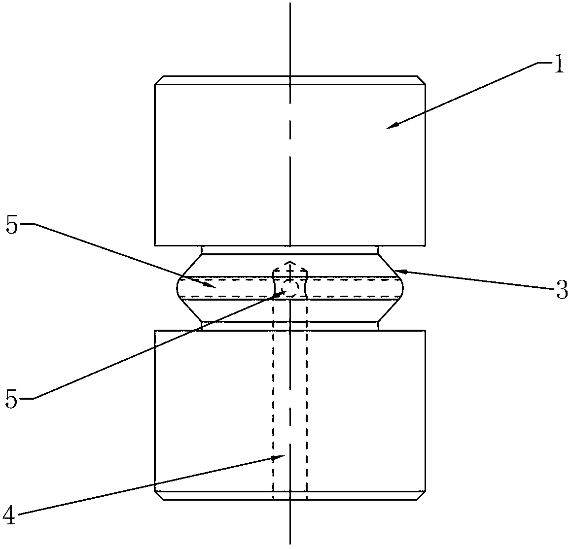
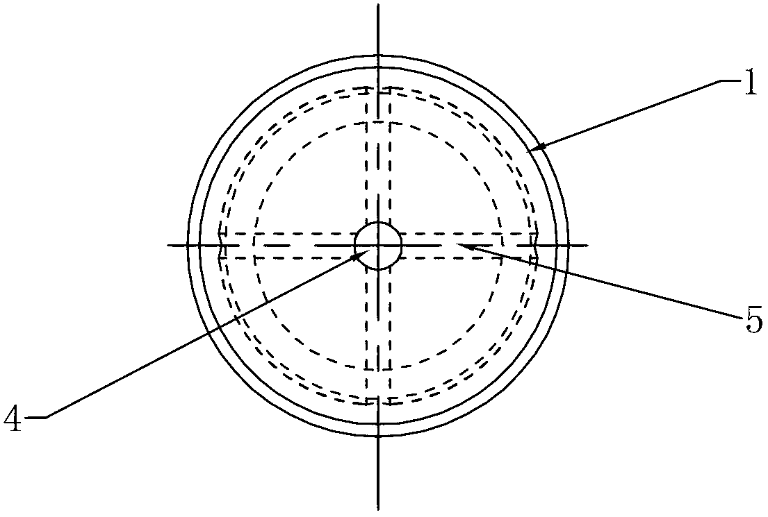
[0015] Such as figure 1 As shown, a piston with a seal in the present invention includes a piston body 1 and a seal 2 . combine Figure 5 , Image 6 As shown, the sealing member 2 is ring-shaped, the section of the sealing member 2 is V-shaped, the opening direction of the V-shaped section is inward, and the sealing member 2 is made of elastic wear-resistant material. combine figure 2 , Figure 4 As shown, the outer peripheral surface of the piston body 1 is provided with an annular groove 3 , and the bottom surface of the annular groove 3 protrudes outward. The sealing member 2 is installed in the annular groove 3, the inner surface of the sealing member 2 fits the bottom surface of the annular groove 3, and the first oil hole 4 is opened on the upper or lower end surface of the piston body 1, the first oil hole 4 is located at the center of the lower end surface of the piston body 1 . combine image 3 As shown, four second oil holes 5 are provided in the middle of th...


PUM


Abstract

The invention relates to a piston for realizing sealing by expanding a sealing piece with hydraulic force. The piston with a sealing piece comprises a piston body and a sealing piece, wherein the sealing piece is annular; the section of the sealing piece is V-shaped; the opening of the V-shaped section faces inwards; the outer circumferential surface of the piston body is provided with an annular groove; the groove bottom surface of the annular groove projects outwards; the sealing piece is arranged in the annular groove; the inner surface of the sealing piece is jointed with the groove bottom surface of the annular groove; the upper end face or the lower end face of the piston body is provided with a first oil hole; the middle part of the groove bottom surface of the annular groove is provided with at least one second oil hole; and each second oil hole is communicated with the first oil hole. The piston has an automatic pressure compensation sealing function, high-pressure oil can be prevented from flowing into the upper part of a piston cylinder from a gap between the piston cylinder and the piston, and hydraulic energy is saved simultaneously.

Description

technical field [0001] The present invention relates to a piston, in particular to a piston that realizes sealing by expanding the sealing member by hydraulic pressure. Background technique [0002] When the piston moves in the piston cylinder, the gap between the piston and the piston cylinder wall is generally sealed by an O-ring, but for some working conditions with high sealing requirements, such as in the piston cylinder, high-pressure oil is passed under the piston, while A spring is connected to the top of the piston, and the piston returns through the spring. If an ordinary sealing ring is used, high-pressure oil will easily flow into the upper part of the piston cylinder from the gap between the piston cylinder and the piston, causing loss of hydraulic oil and polluting the working environment. The gap between the sealing ring and the cylinder wall of the piston cylinder is set very small, although it can reduce the flow of high-pressure oil into the upper part of t...

Claims


Application Information

Patent Timeline
IPC IPC(8): F16J9/08
Inventor 简国雄
Owner 范跃卫
Learn More