Device suitable for dust removal of ore tank

A mine tank and dust hood technology, applied in the field of dust control in production workshops, can solve the problems of increasing system energy consumption, affecting dust removal effect, increasing system failure rate, etc., so as to reduce dust removal energy consumption, improve dust removal effect, and reduce dust removal air volume. Effect

Pending Publication Date: 2022-03-11
CHINA UNIV OF MINING & TECH
View PDF16 Cites 0 Cited by
  • Summary
  • Abstract
  • Description
  • Claims
  • Application Information

AI Technical Summary

Problems solved by technology

However, the dust collector of this type of technical solution needs to run synchronously with the unloading truck, and the dust collector is located indoors, resulting in a great limitation in the volume of the dust collector. Under the demand for reducing the volume of the dust collector, the design upper limit of the dust collector's processing capacity is reduced. , the exhaust air volume at the unloading point is obviously insufficient, and the dust removal effect is not good. At the same time, the dust collector is indoors, and the maintenance work such as dust removal and bag replacement is more difficult, which affects the dust removal effect
In addition, when the dust collector moves with the unloading truck, the cables

Method used


Image

  • Device suitable for dust removal of ore tank
  • Device suitable for dust removal of ore tank
  • Device suitable for dust removal of ore tank

Examples


Example Embodiment

[0026] Example 1:

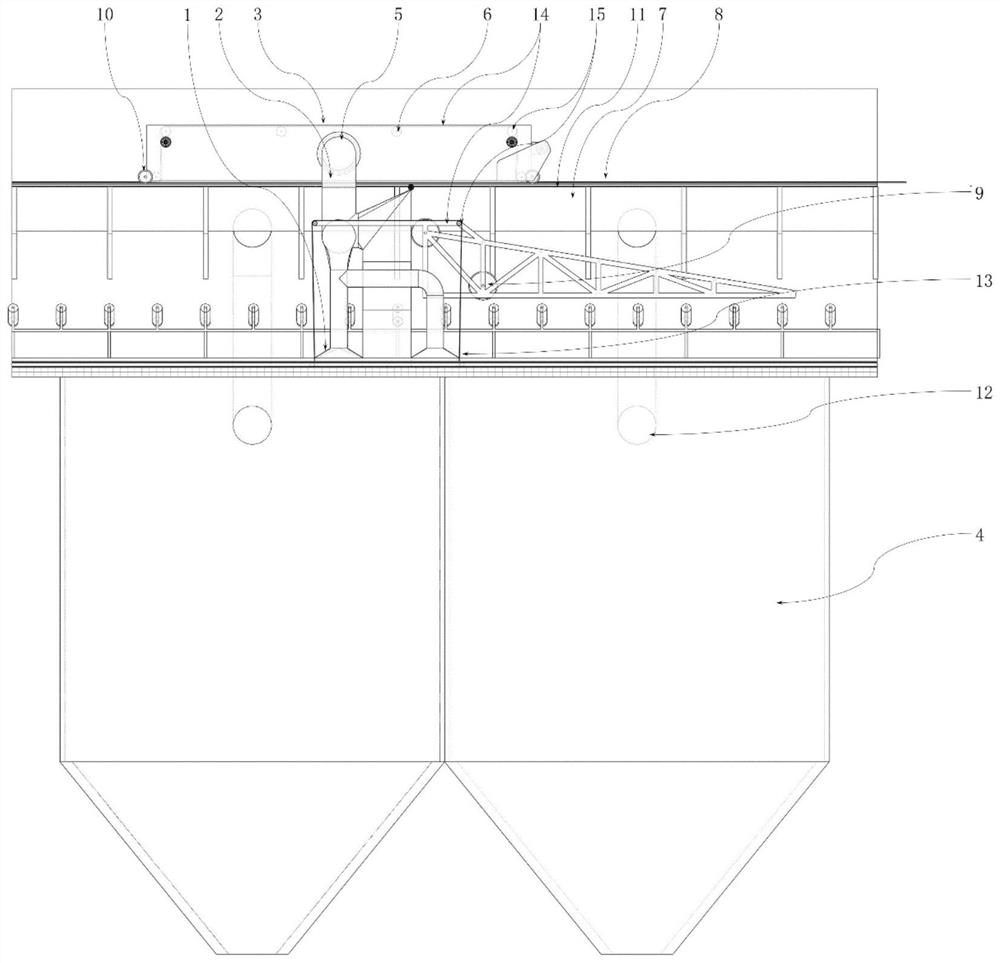
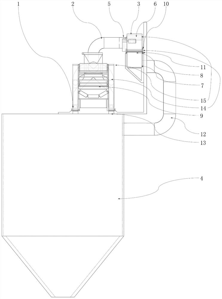
[0027] like figure 1 The above-mentioned device suitable for dust removal in mine tanks includes a dust collection hood 1, a pneumatic conveying pipeline 2, a tape-sealed synchronous transfer system 3 and dust removal equipment. The dust collection hood 1 and the pneumatic conveying pipeline 2 are fixed on the unloading vehicle and move synchronously with it. The dust collection hood is placed above the place where the material and the belt are separated and enters the silo 4. One end of the pneumatic conveying pipeline 2 is connected to the dust collection hood. 1, and the other end is connected to the gas delivery port 5 of the tape-sealed synchronous transfer system 3. The tape-sealed synchronous transfer system 3 includes the gas delivery port 5, the mobile bellows 6, the ventilation slot 7, the ventilation slot opening 8, the rubber Belt 14, rollers 15, and mobile bellows 6 are similar to an inverted U shape, and are movably installed on the upper sur...

Example Embodiment

[0029] Example 2:

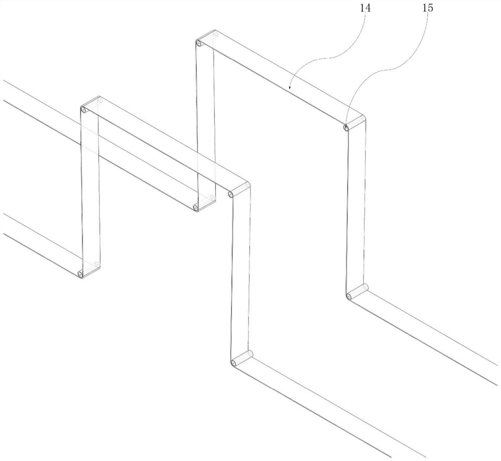
[0030] Compared with Embodiment 1, as an improvement, there are multiple dust suction hoods, which are respectively arranged on the upper part where the material breaks away from the belt and enters the bin 4 and on the mine troughs on both sides of the point where the material falls into the mine chute. There is a pressure sealing device 13, the pressure sealing device includes a rubber belt 14, a roller 15, at least four groups of rollers 15 are arranged at the front and rear ends of the dust collection hood 1 and at the upper turning point, and the rollers 15 at the front and rear ends of the dust collection hood 1 are located The upper part of the rubber belt 14 exerts downward pressure on the rubber belt 14. The roller 15 at the turning point on the upper part of the dust collector 1 is located at the lower part of the rubber belt 14, and is used to change the direction of movement of the rubber belt 14. When the discharge place changes At this time, t...


PUM


Abstract

The dust removal device comprises a dust suction hood, a pneumatic conveying pipeline, an adhesive tape press-sealing type synchronous transfer system and dust removal equipment, the adhesive tape press-sealing type synchronous transfer system comprises an air conveying opening, a movable air bellow, a ventilation groove, a ventilation groove open hole, a rubber belt and a roller, the movable air bellow is in an inverted-U shape and movably installed on the upper surface of the ventilation groove, and the movable air bellow is in an inverted-U shape and movably installed on the lower surface of the ventilation groove. The ventilation groove openings are located in the upper surfaces of the ventilation grooves and are connected with the movable air bellow and the ventilation grooves, and the distance between the ventilation groove openings is smaller than the length of the movable air bellow so that it can be guaranteed that the movable air bellow at least covers one ventilation groove opening at any time; more than one ventilation slot opening is always communicated with the movable air bellow and the ventilation slot, and the movement direction of the rubber belt is changed by utilizing the roller, so that the rubber belt at the place where the movable air bellow passes is lifted, the rest part of the rubber belt presses and seals the ventilation slot opening, and the smoothness of dust removal and ventilation is ensured under the condition of continuous discharging; meanwhile, the ventilation groove opening is adopted to replace a belt gland sealing mode adopted at the upper part of the ventilation groove, so that the sealing effect is better, the dust removal effect can be obviously improved, and the dust removal energy consumption is reduced.

Description

technical field [0001] The invention relates to the technical field of dust control in production workshops, in particular to a dust removal device for mine tank discharge. Background technique [0002] Mineral materials such as raw ore and sintered ore in steelmaking plants are often stored in several silos with a total length of tens of meters. Loaded with ore. When mineral materials are loaded, a large amount of dust escapes due to the large drop of mineral materials, positive pressure in the warehouse, continuous operation and other factors, which brings huge dust pollution in the workshop. [0003] Existing mining trough unloading dust control technologies are mainly divided into two categories, one is the way of ventilation slots combined with an external dust collector, and the other is the way that the dust collector moves synchronously with the unloading truck. [0004] In the way that the ventilation slot cooperates with the external dust collector, the external ...

Claims


Application Information

Patent Timeline
IPC IPC(8): B65G69/18B65G65/32
CPCB65G69/186B65G65/32B65G2201/045
Inventor 李小川张明瑞魏涛何新建周福宝
Owner CHINA UNIV OF MINING & TECH
Why Eureka
Try Eureka