Holder for sensor installation

A retainer and sensor technology, which is applied in the direction of instruments, transportation and packaging, and vehicle safety arrangements, can solve the problems of poor aesthetics, offset between the retainer and the bumper hole, and the reduction of sensor detection accuracy, so as to suppress the increase , The effect of reducing the number of parts and improving the installation operability

Active Publication Date: 2014-10-29
DENSO CORP
View PDF5 Cites 0 Cited by
  • Summary
  • Abstract
  • Description
  • Claims
  • Application Information

AI Technical Summary

Problems solved by technology

[0003] However, since the bumper is not provided with any guides such as protrusions for guiding the retainer to the optimum mounting position on the bumper side, it is difficult to improve the positional accuracy of the retainer relative to the bumper hole, and there is a problem that the retainer is easily damaged. Issues with misalignment with the bumper hole
When such a positional shift occurs, the center of the sensor and the bumper hole will deviate, which will not only deteriorate the aesthetics, but also may reduce the detection accuracy of the sensor

Method used


Image

  • Holder for sensor installation
  • Holder for sensor installation
  • Holder for sensor installation

Examples


Embodiment 1

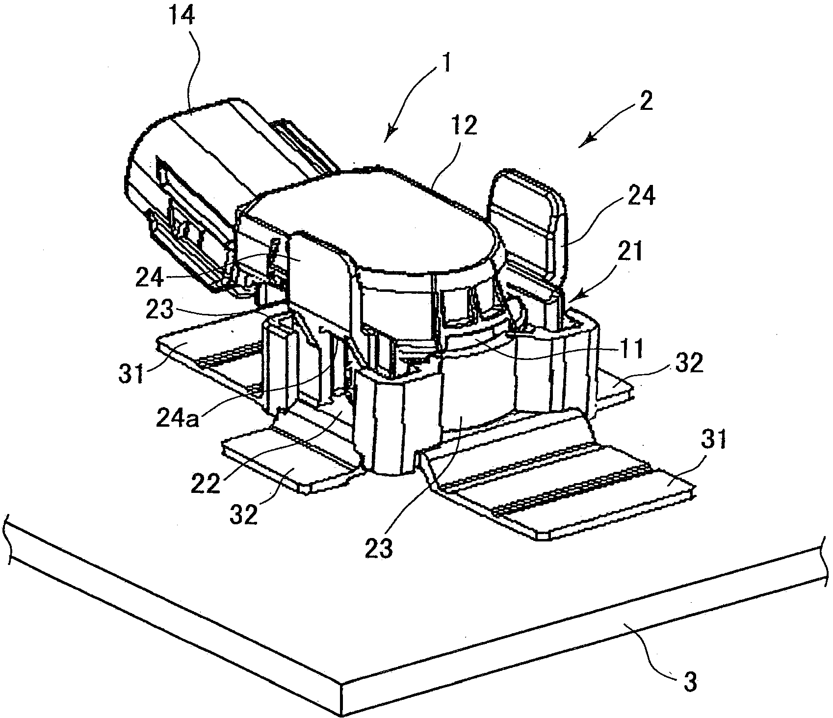
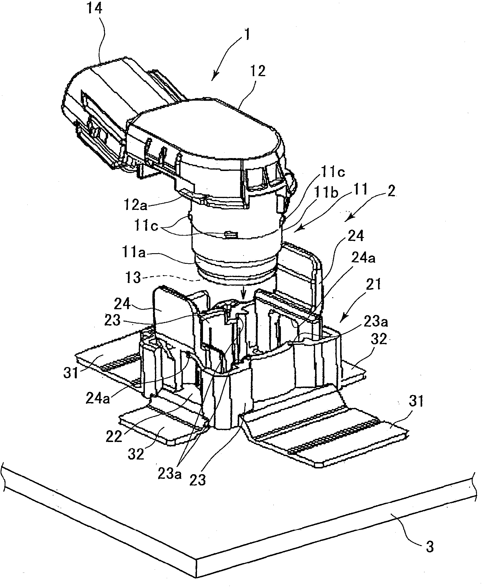
[0053] figure 1 It is a perspective view showing the state where the ultrasonic sensor 1 (hereinafter referred to as the sensor 1 ) is attached to the bumper 3 via the sensor attachment holder 2 (hereinafter referred to as the holder 2 ) according to the first embodiment, figure 2 is a perspective view showing two components before the sensor 1 is mounted on the holder 2 .

[0054] The sensor 1 is a transmitter-receiver type sensor that vibrates a piezoelectric ceramic vibrator by, for example, a piezoelectric effect to emit ultrasonic waves and converts the vibration of the ultrasonic waves incident on the piezoelectric ceramic vibrator into electrical signals, and includes a sensor main body 11, a housing Section 12 et al.

[0055] The sensor main body 11 is formed in a stepped cylindrical shape, and the diameter of the tip portion 11 a (lower end portion) is the smallest. A microphone 13 (detection unit) having a built-in piezoelectric ceramic vibrator is incorporated in...

Embodiment 2

[0087] In the above-mentioned Embodiment 1, the center positioning member 4 and the retainer 2 are made into separate parts in advance, but instead of this structure, for example, Figure 10~Figure 18 As shown, the holder 120 with a centering function may also be formed in which the centering member 140 is integrally formed.

[0088] Such as Figure 15 and Figure 16 As shown, the center positioning member 140 is configured to include: a cylindrical mandrel part 141 ; and a plurality of ribs 142 and spring parts 143 formed on the outer peripheral surface of the mandrel part 141 .

[0089] The core rod portion 141 is formed in a cylindrical shape. The ribs 142 are radially formed at equal angles in the circumferential direction of the core rod part 141 , and are integrally formed on the side surface of the core rod part 141 along the direction of the central axis. In this second embodiment, an example is shown in which three ribs 142 are provided at intervals of 120° in the ...


PUM


Abstract

A maintainer used for installing a sensor, for installing the sensor onto an inner side surface of a fenderguard, comprises: a maintainer main body for supporting the sensor and arranging a sensor main body at a predetermined position; and a pasting part with a tail end part pasted to the fenderguard. The maintainer main body is provided with a maintainer hole. A center positioning component comprises: a core rod part extended along a direction which is coaxial with a central axis of the maintainer hole; a core rod side connecting part which is extended towards a direction far from the core rod part by taking the core rod part as a basal end side and is connected with a maintainer side connecting part to enable the core rod part and the maintainer hole to be arranged coaxially; and a plurality of spring parts which are extended in a circular arc shape by taking the core rod part as a basal end side and perform elastic deformation in the state of contacting with an internal peripheral part of a fenderguard hole to enable the core rod part and the fenderguard hole to be arranged coaxially. Through cooperation between the center positioning component and the maintainer, in the state that the maintainer hole and the fenderguard hole are arranged coaxially, the maintainer is installed to the fenderguard, thus a positional accuracy of the maintainer relative to the fenderguard hole is raised.

Description

technical field [0001] The present invention relates to a sensor attachment holder used when attaching a sensor typified by an ultrasonic sensor to a bumper. Background technique [0002] As a structure for attaching a sensor represented by an ultrasonic sensor to a bumper, there is known a technique in which a retainer is attached to the inner surface (back surface) formed near the bumper hole of the bumper, and the sensor is mounted via the retainer. Attached to a bumper (for example, refer to Patent Document 1). According to such a mounting structure, the sensor can be assembled in the bumper without spoiling the appearance of the bumper. [0003] However, since the bumper is not provided with any guides such as protrusions for guiding the retainer to the optimum mounting position on the bumper side, it is difficult to improve the positional accuracy of the retainer relative to the bumper hole, and there is a problem that the retainer is easily damaged. The issue of mis...

Claims


Application Information

Patent Timeline
Patent Type & Authority Patents(China)
IPC IPC(8): G01S7/521B60R21/00
Inventor 深堀兼史川岛康裕清水忠夫
Owner DENSO CORP
Why Eureka
Try Eureka