Large LED electronic information billboard system
A technology of electronic information and LED driver boards, applied in the direction of electrical digital data processing, instruments, digital output to display equipment, etc., can solve problems such as high operating costs, short life, and impact on perception, and achieve high life, high usability, and environmental protection. High applicability effect
- Summary
- Abstract
- Description
- Claims
- Application Information
AI Technical Summary
Problems solved by technology
Method used
Image
Examples
Embodiment 1
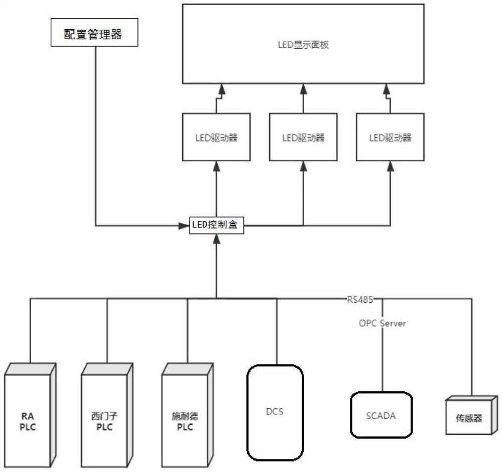
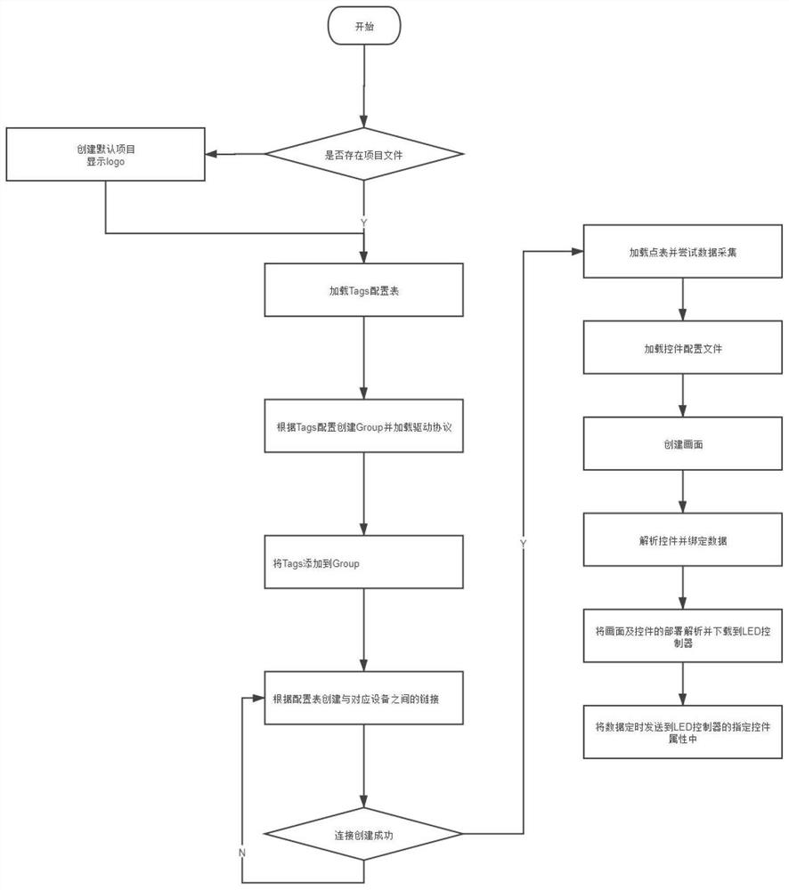
[0029] Example 1: See Figure 1-2 As shown, a large-scale LED electronic information board system includes four parts: 1. LED display panel part; 2. LED driver part; 3. LED main control box; 4. LED screen configuration software.
[0030] in:
[0031] The LED display panel is mainly used for display; the LED panel supports P4 and P5 full-color, and the LED driver board supports pixels ranging from 512x320 to 1024x640. It also supports cascading of multiple LED driver boards to complete the splicing of larger screens. HUB75 standard interface is used to connect the LED panel.
[0032] LED driver is mainly used for the control of LED panel, such as scanning mode, brightness control, panel wiring mode, driver chip, switch screen, etc. It is mainly used to drive the whole LED screen. Due to its large number of scanning points and high scanning frequency, it adopts FPGA design. Program. The LED driver board adopts a controller developed based on FPGA, which mainly realizes the di...
Embodiment 2
[0040] Embodiment 2: On the basis of Embodiment 1, the protocol adapter uses RS485 lines to connect to the underlying system. There are many types of PLCs, including but not limited to RA-PLC, Siemens PLC, Schneider PLC, and LED control boxes Sensors are also connected.
[0041] The working principle is as follows: if figure 2 Shown: The working steps of the LED screen configuration software are as follows: Step 1, start the program; Step 2, create a panel according to the number of dot matrix of the LED screen; Step 3, create a Tags label file; Step 4, create a connection and specify the connection control IP address, port number, communication protocol and other parameters of the device; step 5, create the Tags tag name and specify the address connected to the lower computer; step 6, complete the creation of the tag file; step 7, select the corresponding control to deploy to the panel; step 8. According to the properties of the corresponding controls, bind its properties t...
PUM
 Abstract
Description
Claims
Application Information
 - R&D
- Intellectual Property
- Life Sciences
- Materials
- Tech Scout
- Unparalleled Data Quality
- Higher Quality Content
- 60% Fewer Hallucinations
Browse by: Latest US Patents, China's latest patents, Technical Efficacy Thesaurus, Application Domain, Technology Topic, Popular Technical Reports.
© 2025 PatSnap. All rights reserved.Legal|Privacy policy|Modern Slavery Act Transparency Statement|Sitemap|About US| Contact US: help@patsnap.com


