Auxiliary device for metallographic specimen grinding and polishing machine
An auxiliary device, metallographic sample technology, applied in surface polishing machine tools, grinding/polishing equipment, preparation of test samples, etc. The working principle is simple, the grinding and polishing efficiency is improved, and the operation is convenient and quick.
- Summary
- Abstract
- Description
- Claims
- Application Information
AI Technical Summary
Problems solved by technology
Method used
Image
Examples
Embodiment 1
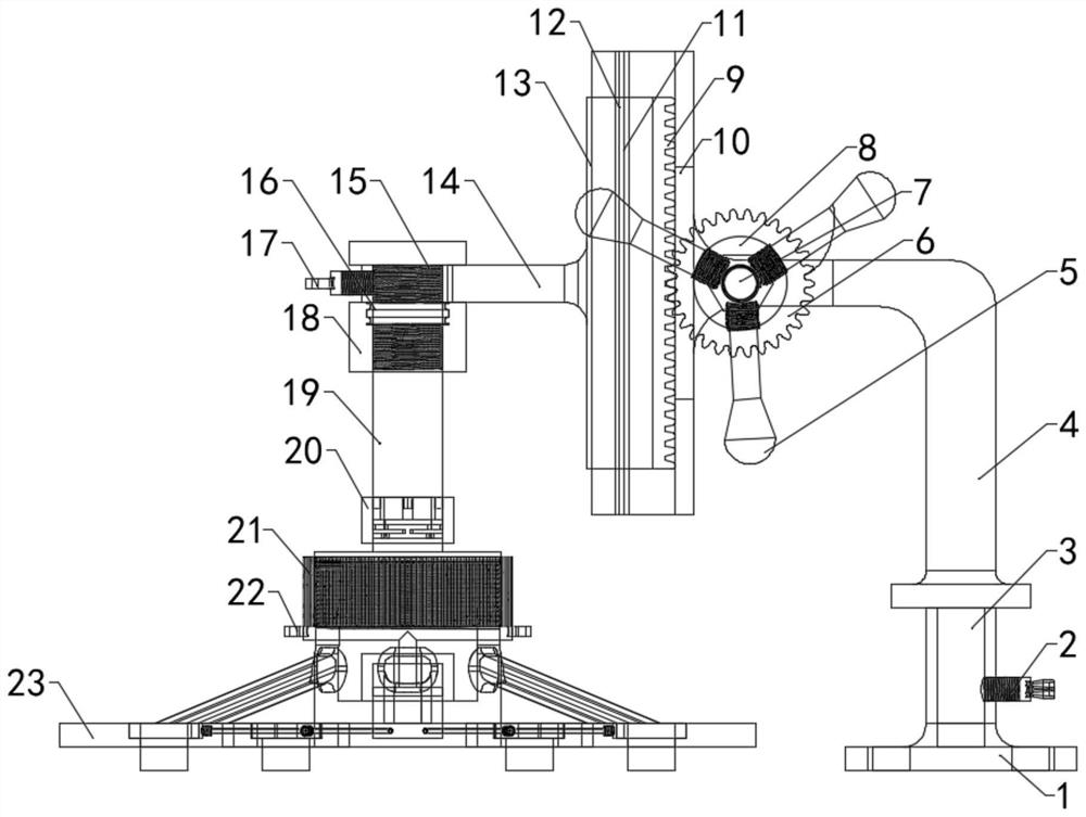
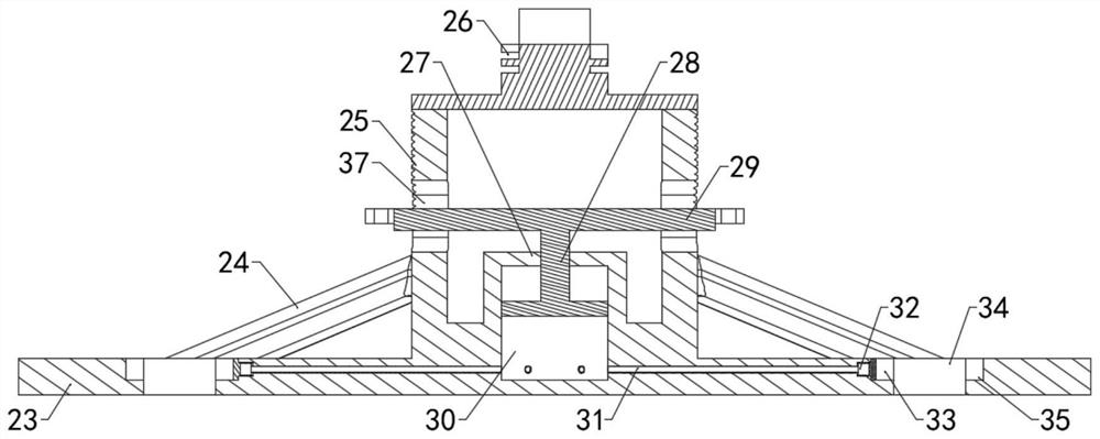
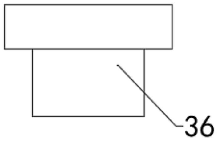
[0034] like Figure 1-Figure 4 As shown, an auxiliary device for a metallographic sample grinding and polishing machine includes a base 1, a grinding and polishing pressure plate 23, and a plurality of sample grooves 35 and sampling grooves 34 are evenly distributed on the grinding and polishing pressure plate 23. The sample 36 is located in the sample groove 35 to realize simultaneous grinding and polishing of a plurality of metallographic grinding and polishing samples 36. The sample groove 35 is located directly above the sampling groove 34, and the cross-section of the sample groove 35 is circular, and The longest distance between the two end points on the sampling groove 34 is greater than the diameter of the sample groove 35, and the shortest distance between the two end points on the sampling groove 34 is less than the diameter of the sample groove 35. Grind and polish the evenly distributed oblique support rods 24 and medium on the pressure plate 23. The design of the ...
Embodiment 2
[0038] In order to adjust the position of the grinding and polishing platen, such as figure 1 , Figure 5 and Image 6As shown in the figure, the base 1 is provided with a positioning hole for installing the auxiliary device on the metallographic sample grinding and polishing machine, so that the auxiliary device can be directly installed on the grinding and polishing machine without changing the original metallographic grinding and polishing machine, and the base 1 is rotated to connect There is a support frame 4, and there is a clearance fit between the support frame 4 and the base 1, and a rotating shaft 3 is installed at the bottom end of the support frame 4, the rotating shaft 3 is located in the base 1, and the rotating shaft 3 and the base 1 are rotatably connected , the base 1 is threadedly connected with a butterfly bolt 1 2, the axis of the butterfly bolt 1 is perpendicular to the axis of the rotating shaft 3, the rotating shaft 3 is fixed by tightening the butterfl...
Embodiment 3
[0043] In order to ensure the accuracy of the upper and lower positions of the grinding and polishing platen 23, such as figure 1 , Figure 7 and Figure 8 As shown, the lateral support 14 is provided with a positioning shaft hole 15 and an annular raised portion 1401, the annular raised portion 1401 is coaxial with the positioning shaft hole 15, and the annular raised portion 1401 is located below the positioning shaft hole 15. An annular groove 16 is provided on the outer wall of the annular raised portion 1401 , a fine adjustment screw sleeve 18 is sleeved on the annular raised portion 1401 , and the fine adjustment threaded sleeve 18 is provided with an annular raised groove and a thread matched with the annular groove 16 . , a movable shaft 19 is installed in the positioning shaft hole 15, and the movable shaft 19 is connected with the positioning shaft hole 15 and the fine adjustment screw sleeve 18 by threads. The slot structure is connected with the card slot 26 thro...
PUM
 Abstract
Description
Claims
Application Information
 - R&D
- Intellectual Property
- Life Sciences
- Materials
- Tech Scout
- Unparalleled Data Quality
- Higher Quality Content
- 60% Fewer Hallucinations
Browse by: Latest US Patents, China's latest patents, Technical Efficacy Thesaurus, Application Domain, Technology Topic, Popular Technical Reports.
© 2025 PatSnap. All rights reserved.Legal|Privacy policy|Modern Slavery Act Transparency Statement|Sitemap|About US| Contact US: help@patsnap.com


