Split joint type large-area field emission planar light source

A planar light source and field emission technology, applied in the direction of fluorescent screen lamps, etc., can solve the problems of poor vacuum degree, difficulty in obtaining large-area planar light source, and inability to meet the level of field emission planar light source, so as to achieve the effect of improving uniformity and prolonging life

Inactive Publication Date: 2010-09-01
FUZHOU UNIV
View PDF3 Cites 4 Cited by
  • Summary
  • Abstract
  • Description
  • Claims
  • Application Information

AI Technical Summary

Problems solved by technology

However, this arrangement of the getter results in a better vacuum at a position close to the getter inside the field emission planar light source, and a poorer vacuum at a position far away from the getter.
Generally speaking, at a distance of about 5 cm away from the getter, the vacuum degree drops by about three orders of magnitude, which cannot meet the level required for the normal operation of a field emission planar light source, and it is difficult to obtain a large-area, uniform field emission plane. light source

Method used


Image

  • Split joint type large-area field emission planar light source
  • Split joint type large-area field emission planar light source
  • Split joint type large-area field emission planar light source

Examples


Embodiment 2

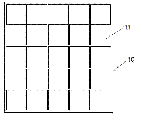
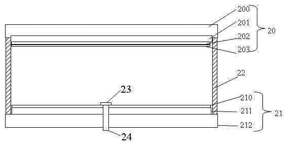
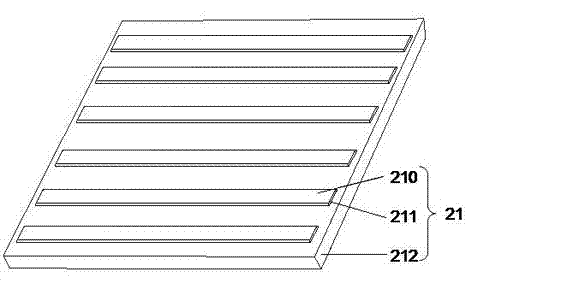
[0030] refer to Figure 4 and Figure 5 , Figure 4 It shows a schematic diagram of a spliced ​​large-area field emission planar display light source in Embodiment 2 of the present invention, Figure 5A three-dimensional exploded schematic diagram showing a single circular field emission light source unit. In this embodiment, the spliced ​​large-area field emission flat display light source 40 includes 40 field emission light source units 41 without vacuum isolation pillars, and the 40 field emission light source units 41 without vacuum isolation pillars are independently arranged on a plane , and arranged in 5 rows and 8 columns, combined into a splicing large-area field emission backlight 40; wherein there is no field emission light source unit 41 for vacuum isolation pillars; the field emission light source unit 41 without vacuum isolation pillars includes a cathode plate 51 , an anode plate 50 corresponding to the cathode, an edge sealing body 52 and a getter 53 for enc...


PUM


Abstract

The invention relates to a split joint type large-area field emission planar light source, which comprises a plurality of non-vacuum isolation strut field emission light source units. The plurality of non-vacuum isolation strut field emission light source units are mutually independently arranged on a plane and arranged and combined to form a large-area field emission backlight; and the field emission light source unit comprises a cathode plate, an anode plate corresponding to the negative plate, an edge sealing body for packing a cathode and an anode, a getter and an exhaust pipe. The split joint type large-area field emission planar light source solves the problems that vacuum isolation struts in a field emission device have charge accumulation and difficult maintenance of vacuum degree without the vacuum isolation struts, effectively prolongs the service life of a field emission illumination light source, improves the luminous uniformity, and realizes illumination application of the large-area field emission planar light source.

Description

technical field [0001] The invention relates to a large-area field emission planar light source, in particular to a splicable large-area field emission planar light source. Background technique [0002] In recent years, planar light sources have been widely used in many fields, especially in the field of information display. As a green energy-saving lighting source, the field emission planar light source uses the cathode material on the plane to bombard the anode phosphor under the action of an electric field to emit uniform visible light. [0003] At present, large-area planar light sources are mainly assembled by multiple traditional fluorescent lamps or semiconductor light-emitting diodes, and are used for outdoor large-area lighting or display. However, fluorescent lamps and semiconductor light-emitting diodes have disadvantages such as environmental pollution and high cost, which limit their application in large-area lighting or display. Compared with other planar lig...

Claims


Application Information

Patent Timeline
Patent Type & Authority Applications(China)
IPC IPC(8): H01J63/06
Inventor 叶芸郭太良张永爱游玉香胡利勤
Owner FUZHOU UNIV
Why Eureka
Try Eureka