Plate Fixed Heating Unit Device

A heating unit and board technology, applied in heating methods, lighting and heating equipment, household heating, etc., can solve the problems of easy deformation, large gap between boards, no heating, heat preservation and moisture resistance, etc., and achieve fast heating speed, uniform heating, The effect of large specific heat capacity

Inactive Publication Date: 2011-12-14
杨中竣
View PDF5 Cites 4 Cited by
  • Summary
  • Abstract
  • Description
  • Claims
  • Application Information

AI Technical Summary

Problems solved by technology

Through the valve installed on the water separator, the temperature controllable range is small and cannot be precisely controlled
[0011] At present, the boards are installed with cement or adhesives when laying. After installation, the gap between the boards is relatively large, and it is impossible to realize the effect that no obvious gaps can be seen after the combined laying. Its d

Method used


Image

  • Plate Fixed Heating Unit Device
  • Plate Fixed Heating Unit Device
  • Plate Fixed Heating Unit Device

Examples


Embodiment 1

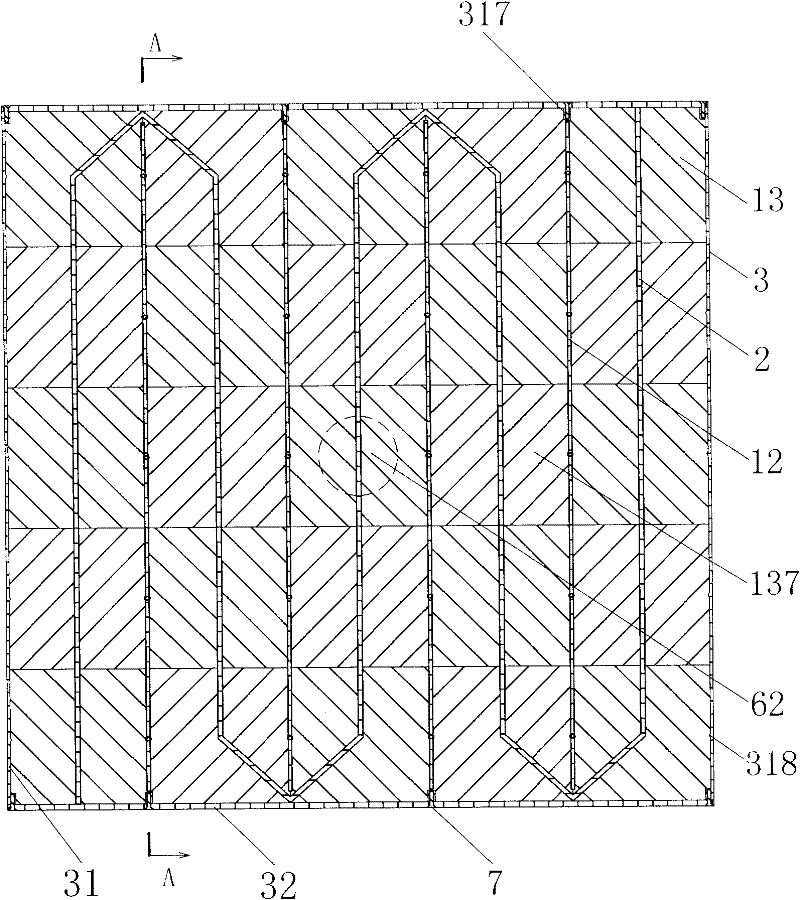
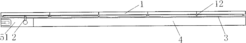
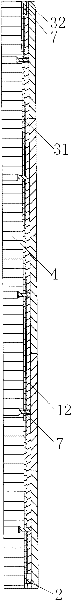
[0118] Embodiment 1: as figure 1 , figure 2 , image 3 , Figure 15 As shown, the present invention includes a decorative board layer 1, a connecting frame 3 and a moisture-proof and heat-insulating layer 4 of a built-in heating device 2 arranged in sequence, and also includes a fixed lock 6 arranged on the connecting frame 3 and the moisture-proof and heat-preserving layer 4 and a moisture-proof and heat-preserving layer. Two electrical connection blocks for layer 4; as figure 2 As shown, the first electrical connection block 51 and the second electrical connection block 52 are respectively placed on two opposite corners of the moisture-proof insulation layer 4, arranged in antiparallel, the heating device 2 is built into the decorative board layer 1, and the two ends are respectively connected to the second 1. The second electrical connection blocks 51 and 52 are connected, and when assembled, the ends of the electrical connection blocks of the two unit devices are in c...

Embodiment 2

[0130] Embodiment 2: The overall structure of this embodiment is the same as that of Embodiment 1. The difference is that in this embodiment, the decorative layer 1 is composed of two bricks 13. In this embodiment, two glue-injected first electrical connection blocks 51 are placed On the two adjacent corners of the moisture-proof insulation layer 4, the same direction is arranged in parallel. The first stiffener 12 that adopts in this example, as Figure 19 , Figure 19 (a), Figure 19 As shown in (b), its cross-section is a trapezoidal structure with a first threaded hole protrusion 121 on it. In this example, on the two frames of the first main board bracket 31 where the first side plate 32 is installed, there are symmetrically respectively a heating wire outlet 314 and a third bolt hole protrusion 317 for fixing the first side plate 32, and there are holes on the thin plate for The first bolt hole 312 of the second reinforcing rib 14 is fixed. In order to make the prese...

Embodiment 3

[0131] Embodiment 3: The overall structure of this embodiment is the same as that of Embodiment 1, the difference is that in this embodiment, the decorative plate layer 1 is composed of 9 bricks 13 . The first stiffener 12 section that adopts in this example is triangular and the arched structure that combines with triangular one side, and Figure 25 , Figure 25 (a), Figure 25 The second reinforcing rib 14 shown in (b) has the same structure, and has a second threaded hole protrusion 141 for fixing the reinforcing rib of this example. Its installation method is identical with embodiment 1.


PUM


Abstract

The invention discloses a plate fixing and heating unit device belonging to the technical field of heat supply and heating. The plate fixing and heating unit device comprises a decorative plate layer internally provided with a heat supply device, a connecting frame and a moisture-proof insulating layer that are sequentially arranged. The plate fixing and heating unit device also comprises a fixedlock arranged between the connecting frame and the moisture-proof insulating layer, and two electrical-connecting blocks arranged on the moisture-proof insulating layer, wherein the two electrical-connecting blocks are respectively a first and a second electrical-connecting blocks when being respectively arranged on two opposite corners of the moisture-proof insulating layer, and are arranged in a negative parallel manner; the two electrical-connecting blocks are respectively first electrical-connecting blocks when being respectively arranged on two adjacent corners of the moisture-proof insulating layer, and are arranged in an equidirectional parallel manner; the heat supply device is arranged in the decorative plate layer, two ends of the heat supply device are respectively connected with the two electrical-connecting blocks; and during the assembly, the electrical-connecting blocks of two unit devices are in mutual contact. The invention can realize the advantages of uniformity in heating, high heat-radiating speed, no need of laying pipelines and damaging family decoration, simpleness in installation, random disassembly, recycling property, good stability, long service life, complete waterproof property, and resistance to pressure and expansion caused by heat and contraction caused by cold, and can be used in floor, bed surface and wall surface heat supply.

Description

technical field [0001] The invention belongs to the technical field of heating and heating, and in particular relates to a plate-fixed heating unit device. Background technique [0002] From the south of the Huaihe River to the Yangtze River Basin and the Central Plains and Northwest China, the temperature in winter is below zero degrees Celsius. The central and western regions of China often suffer from snowstorms and freezing weather in winter. These regions in China do not have perfect winter heating facilities, which makes these Residents of the region suffer conservatively during winter. It is very difficult to build centralized heating facilities here. Unlike the north, the construction of heating facilities has been completed in the urban construction planning in these areas, and the urban planning and construction in these areas have been completed, so it is very difficult to build centralized heating facilities now. , There will be a lot of funds to be used. The co...

Claims


Application Information

Patent Timeline
IPC IPC(8): F24D13/00F24D19/00
Inventor 杨中竣
Owner 杨中竣
Why Eureka
Try Eureka