Collecting tank of a heat exchanger

A technology for heat exchangers and heat exchanger tubes, applied in the field of collection tanks, can solve the problems of uneven contact between the bottom and the heat exchanger tubes, a large number of heat exchangers, and a large installation space, and achieve cost-effective manufacturing and more installation space. , the effect of improving efficiency

Inactive Publication Date: 2019-04-30
MAHLE INT GMBH
View PDF10 Cites 0 Cited by
  • Summary
  • Abstract
  • Description
  • Claims
  • Application Information

AI Technical Summary

Problems solved by technology

This also leads to extensive and / or expensive manufacture of the collecting tank and thus the heat exchanger
This also results in uneven contact between the bottom and the heat exchanger tubes and requires a larger installation space

Method used


Image

  • Collecting tank of a heat exchanger
  • Collecting tank of a heat exchanger
  • Collecting tank of a heat exchanger

Examples


Embodiment Construction

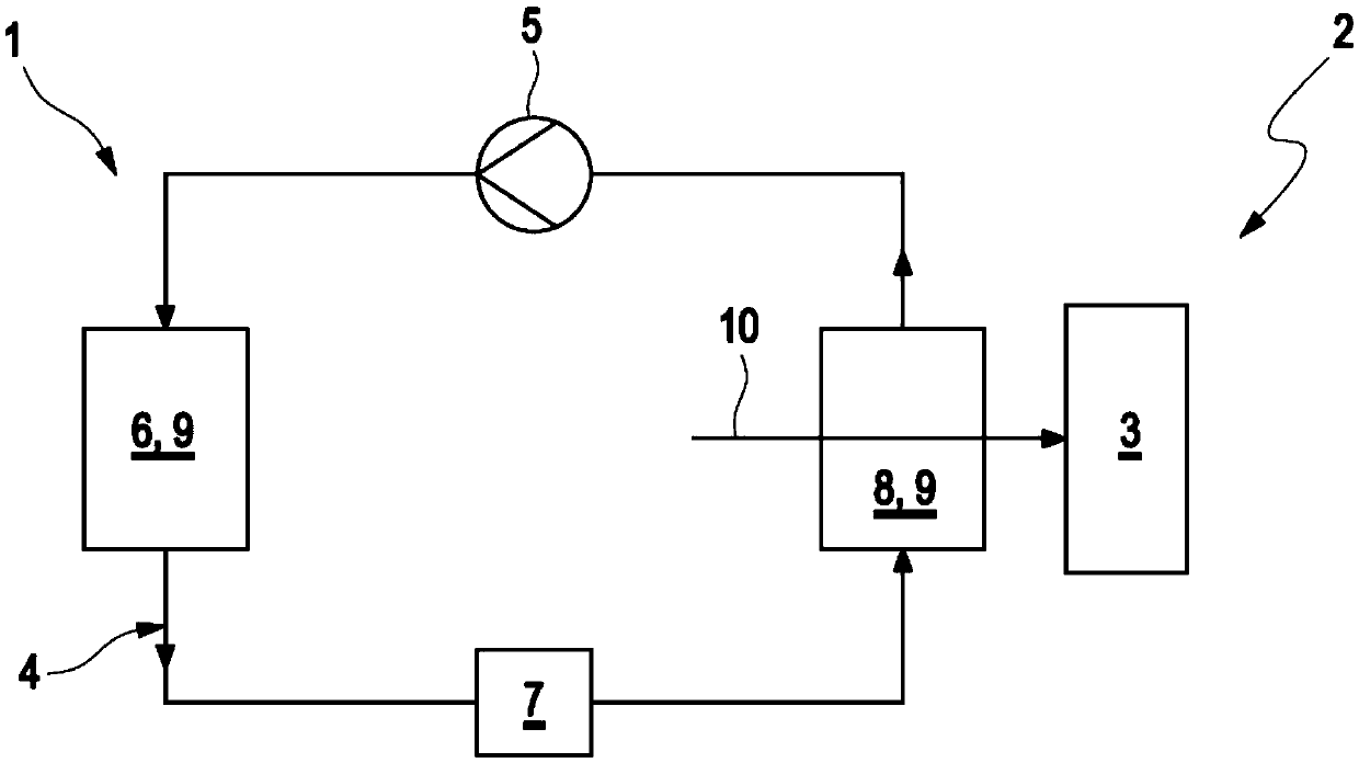
[0039] exist figure 1 An air-conditioning system 1 that can be used in a vehicle 2 for, for example, climate-conditioning a vehicle interior 3 of the vehicle 2 is illustrated in a highly simplified manner. The air conditioning system 1 has a circuit 4 in which a coolant is driven and circulated by a conveying device 5 . The coolant thus flows successively through the capacitor 6 , the expander 7 and the evaporator 8 , wherein the capacitor 6 and the evaporator 8 serve in each case as a heat exchanger 9 . The coolant and the further fluid flow through the corresponding heat exchanger 9 in such a way that heat exchange takes place between the coolant and the further fluid. In the case of the evaporator 8 , the further fluid is air 10 , which flows through the evaporator 8 and is thereby cooled, wherein the cooled air 10 is supplied to the vehicle interior 3 .

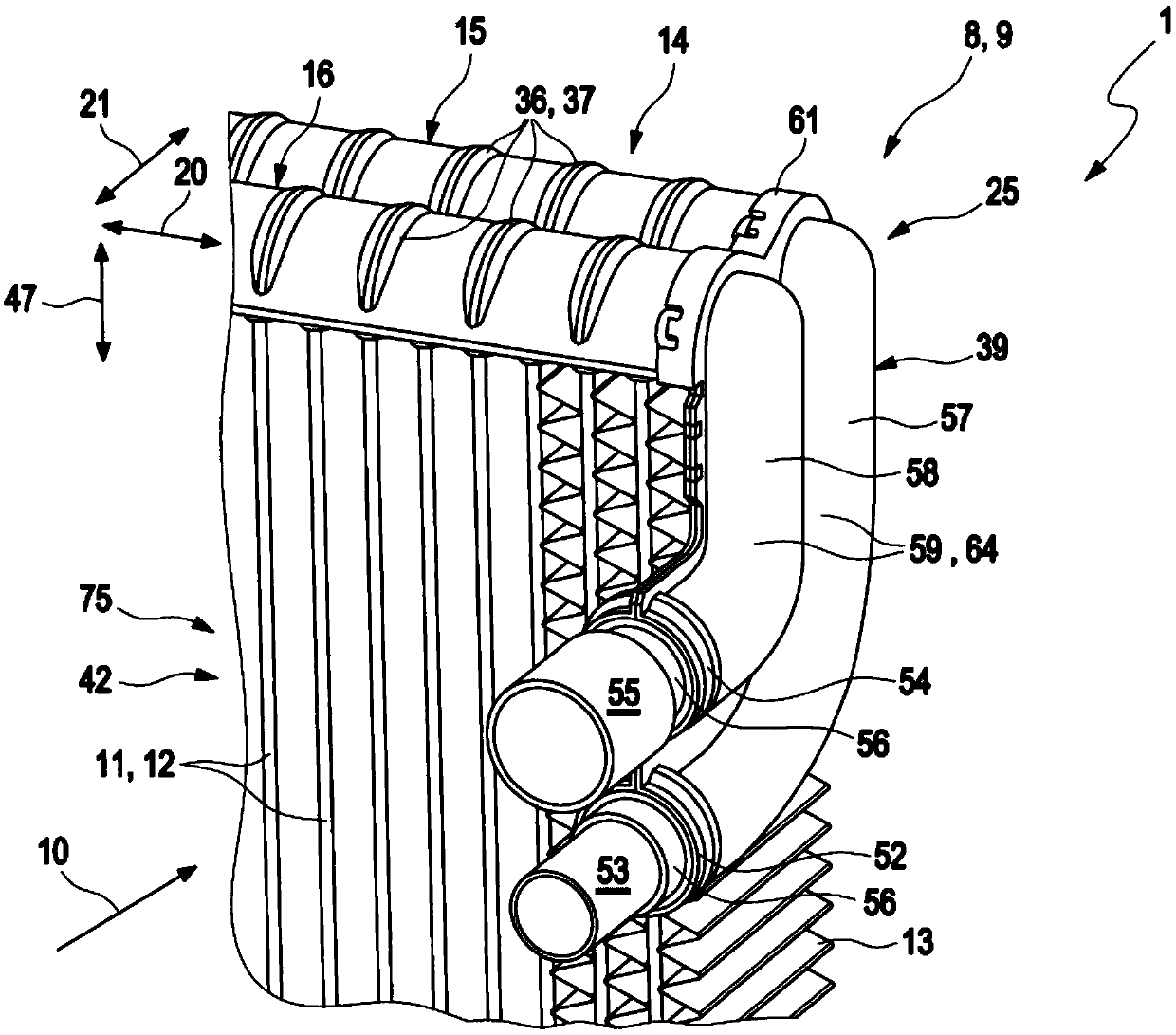
[0040] figure 2 An isometric partial view of a heat exchanger 9, in particular an evaporator 8, is shown. The heat...


PUM


Abstract

The present invention relates to a collecting tank (14) of a heat exchanger (9), which comprises flat bottoms (17) that are adjacently configured and respectively have a tank accommodating space (24)for accommodating a heat exchanger pipe (11) of a heat exchanger (9). The invention realizes an embodiment with reduced mounting space of the collecting tank (4) and the heat exchanger (9) and/or improved efficiency through a fact that the bottoms (17) of the collecting pipes (15,16) obliquely extend relative to each other. The invention further relates to a heat exchanger (9), particularly an evaporator (8) comprising the collecting tank (14).

Description

technical field [0001] According to the preamble of claim 1 , the invention relates to a collecting tank of a heat exchanger, in particular of an evaporator. The invention also relates to a heat exchanger comprising such a collection tank. Background technique [0002] Heat exchangers are used for the purpose of exchanging heat between two fluids. One of these fluids flows, usually via a collecting tank, through heat exchanger tubes around which the other fluid flows so that heat is exchanged between the two fluids. As a result of the resulting temperature difference, condensate accumulates inside the heat exchanger, especially when gas, such as air, flows around the heat exchanger tubes. This accumulated condensate needs to be drained in order to achieve trouble-free operation of the heat exchanger and / or an increased efficiency of the heat exchanger. [0003] From CA 2123368 A1 is known a heat exchanger comprising a collecting tank with two collecting tubes each compris...

Claims


Application Information

Patent Timeline
Patent Type & Authority Applications(China)
IPC IPC(8): F28F17/00
CPCF28F17/005F25B2500/01F28F9/02F28F9/0246F28D1/05391F28D2021/0085F28F2009/0292F25B39/02F24F13/222
Inventor 戈特弗里德·迪尔阿克塞尔·多尔德雷理查德·戈采哈拉尔德·米莱森本亚明·诺特杜尔福特马库斯·普夫利格
Owner MAHLE INT GMBH
Why Eureka
Try Eureka