Method and device for configuring receiving filter

A receiving filter and configuration method technology, applied in the direction of data exchange through path configuration, digital transmission system, electrical components, etc., can solve the problems of low accuracy and low efficiency, and achieve the effect of ensuring accuracy and automatic high-efficiency configuration

Active Publication Date: 2014-12-17
BEIJING JINGWEI HIRAIN TECH CO INC
View PDF2 Cites 0 Cited by
  • Summary
  • Abstract
  • Description
  • Claims
  • Application Information

AI Technical Summary

Problems solved by technology

[0006] In view of this, the present invention provides a receiving filter configuration method and device to overcome the problems of low efficiency and low accuracy in the prior art due to manual configuration of identifier receiving filters

Method used


Image

  • Method and device for configuring receiving filter
  • Method and device for configuring receiving filter
  • Method and device for configuring receiving filter

Examples


Embodiment 1

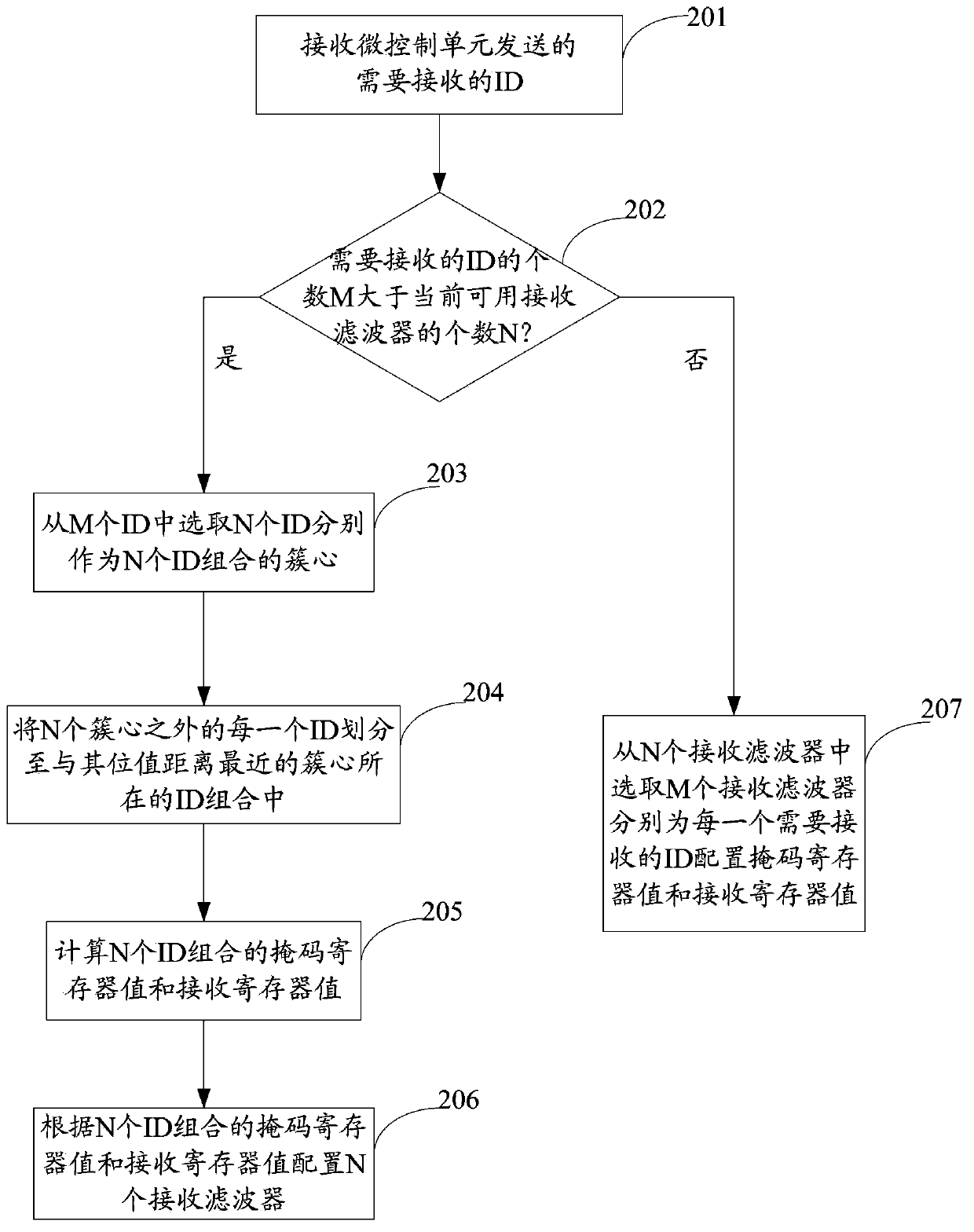
[0055] figure 2 For the flow chart of the configuration method of the receiving filter disclosed in the embodiment of the present invention, see figure 2 As shown, the method may include:

[0056] Step 201: Receive the ID that needs to be received sent by the micro control unit.

[0057] To realize the automatic configuration of the receiving filter, it is first necessary to know what kind of ID the receiving filter needs to receive, so as to configure related parameters, and then select the ID that the node where the receiving filter is located needs to receive from the large number of IDs on the bus.

[0058] Step 202: Determine whether the number M of IDs to be received is greater than the number N of currently available receiving filters; if yes, go to step 203; if not, go to step 207.

[0059] Wherein, the M and the N are positive integers. The purpose of step 202 is to determine whether the IDs to be received need to be grouped.

[0060] Step 203: Select N IDs from...

Embodiment 2

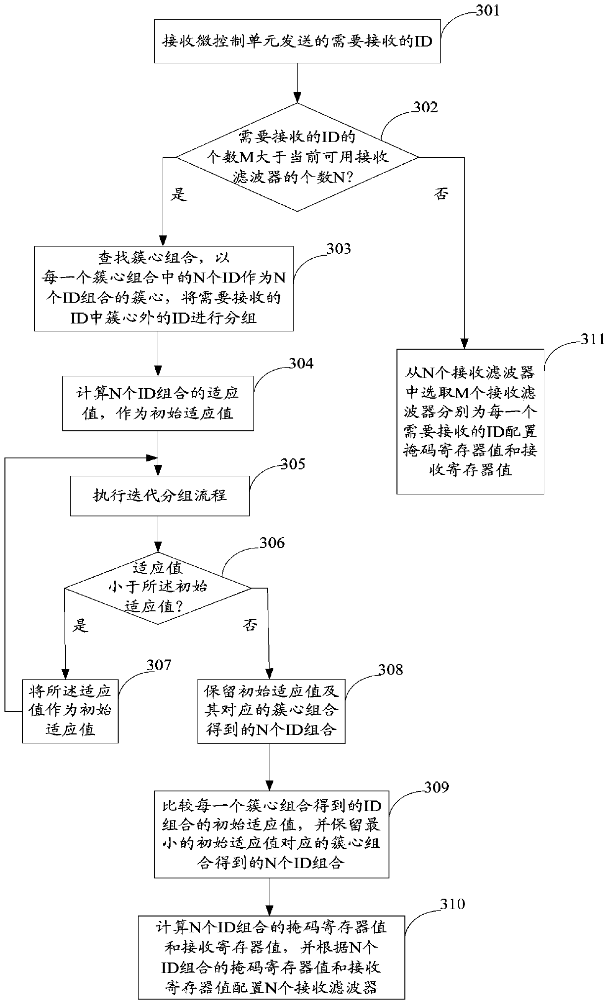
[0079] image 3 For the flow chart of another method for configuring a receive filter disclosed in an embodiment of the present invention, see image 3 As shown, the method may include:

[0080] Step 301: Receive the ID to be received sent by the micro control unit.

[0081] Step 302: Determine whether the number M of IDs to be received is greater than the number N of currently available receiving filters; if yes, go to step 303; if not, go to step 311.

[0082] Wherein, the M and the N are positive integers;

[0083] Step 303: Find cluster center combinations, and use N IDs in each cluster center combination as the cluster centers of the N ID combinations, and group the IDs that need to be received outside the cluster centers.

[0084] Wherein, the cluster center combination includes N cluster centers. Since the cluster center itself is also an ID, the N cluster centers are N IDs. These N IDs are the cluster centers of the N ID combinations, and they are among the IDs that...

Embodiment 3

[0110] Figure 5 For a schematic structural diagram of a receiving filter configuration device disclosed in an embodiment of the present invention, see Figure 5 As shown, the receiving filter configuration device 50 may include:

[0111] The ID receiving module 501 is configured to receive the ID that needs to be received sent by the micro control unit.

[0112] A value judging module 502, configured to judge whether the number M of IDs to be received is greater than the number N of currently available receiving filters.

[0113] Wherein, the M and the N are positive integers.

[0114] Grouping configuration module 503, the grouping configuration module includes a cluster center selection module, an ID grouping module, a numerical calculation module and a numerical configuration module; the cluster center selection module is used for the case where the judgment result of the numerical judgment module 502 is yes Next, select N IDs from the M IDs as the cluster centers of th...


PUM


Abstract

The invention discloses a method and a device for configuring a receiving filter. According to the method, the method for configuring the receiving filter can be determined according to the relationship between the number of ID required to be received and the number of the current available receiving filters; and the method comprises the following steps of: dividing the ID required to be received into a plurality of combinations when the number of ID required to be received is greater than the number of the current available receiving filters, and configuring the mask register value and the receiving register value of the receiving filter according to elements in each combination; and when the number of ID required to be received is smaller than or equal to the number of the current available receiving filters, independently configuring a receiving filter for each ID required to be received so as to receive the ID. According to the method and the device for configuring the receiving filter, the receiving filter can be automatically and efficiently configured, and the accuracy rate of the configuration rate is guaranteed.

Description

technical field [0001] The present invention relates to the field of bus communication, and more specifically, relates to a configuration method and device of a receiving filter. Background technique [0002] As one of the hotspots in today's automation technology development, fieldbus technology provides strong technical support for the distributed control system to realize real-time and reliable data communication between nodes. In order to meet the more and more complex functional requirements and higher performance requirements of automation equipment for the majority of users, each node on the distributed control system must have a good filtering function in the face of a large amount of communication data on the bus. [0003] Each node in the distributed control system includes a micro control unit, a transmitter and a receiver. Among them, the micro control unit is responsible for all calculations of node functions; the sending end is responsible for packaging and se...

Claims


Application Information

Patent Timeline
Patent Type & Authority Patents(China)
IPC IPC(8): H04L12/40H04L12/413
Inventor 张静静李晓琴贾晓
Owner BEIJING JINGWEI HIRAIN TECH CO INC
Why Eureka
Try Eureka