Special drilling machine for processing porous gear

A technology of gears and drilling machines, applied in boring/drilling, metal processing equipment, drilling/drilling equipment, etc., can solve the problems of inconvenient positioning of gears, frequent operations, low production efficiency, etc. The effect of reducing production costs and improving production efficiency

Active Publication Date: 2012-12-05
ZHEJIANG ZHONGCHAI MACHINERY
View PDF6 Cites 25 Cited by
  • Summary
  • Abstract
  • Description
  • Claims
  • Application Information

AI Technical Summary

Problems solved by technology

Its disadvantages are: 1. Ordinary drilling machines can only drill one hole on the gear at one time, and then have to adjust the gear or move the position of the drill bit to drill the second hole. The production efficiency is low, the number of operations is frequent, and it is not convenient to use.
2. Ordinary drilling machines need to continuously add coolant to the drill bit and gear during the drilling process, and the coolant is relatively large when used.
3. Ordinary drilling machines do not have special fixtures for fixing gears, and the positioning of gears is not convenient enough when drilling gears

Method used


Image

  • Special drilling machine for processing porous gear
  • Special drilling machine for processing porous gear
  • Special drilling machine for processing porous gear

Examples


Embodiment Construction

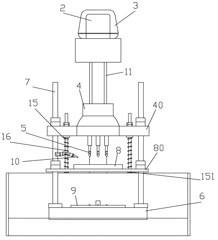
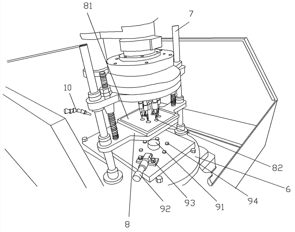
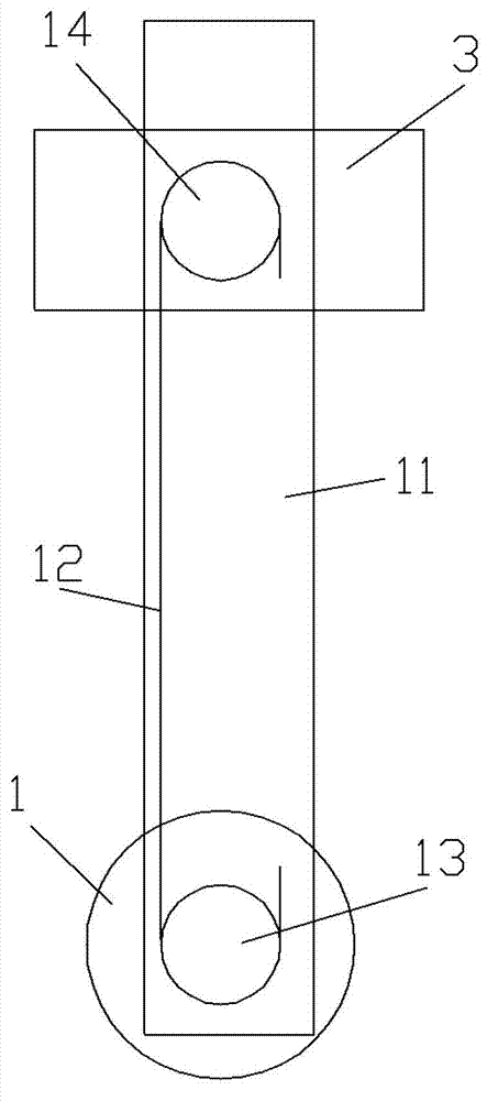
[0020] Example: see Figures 1 to 4 As shown, the special drilling machine for porous gear processing includes a lifting motor 1 and a drilling motor 2. The drilling motor 2 is fixed on the lifting frame 3. The rotating shaft of the drilling motor 2 is fixed on the driving gear 41 of the planetary gearbox 4. There are several driven gears 42 in an annular array on the periphery of the gear 41, the driven gears 42 mesh with the driving gear 41, and the drill bit 5 is fixed on the rotating shaft of the driven gear 41;

[0021] A column 7 is fixed on the workbench 6, a gear box insert plate 40 is formed or fixed on the planetary gearbox 4, the gear box insert plate 40 is inserted on the column 7, and a cooling insert plate 80 is formed on the cooling platen 8 , the cooling sleeve plate 80 is inserted on the column 7;

[0022] The middle part of the cooling platen 8 is formed with a liquid tank 81, and the bottom of the liquid tank 81 is formed with a through hole 82, and the dri...


PUM


Abstract

The invention relates to a special drilling machine for processing a porous gear. A lifting frame can lift; a liquid storing tank is formed in the middle of a cooling bedplate; a through hole is formed at the bottom of the liquid storing tank; a drill bit is aligned with the through hole; the cooling bedplate is sleeved on a slide rod; one end of a spring is pressed on a gearbox sleeve plate; the other end of the spring is pressed on the cooling bedplate; the upper part of the slide rod is fixed on the gearbox sleeve plate; a gear clamp is fixed on an operation platform; the gear clamp is composed of a central positioning pin, a positioning screw rod and a screw rod fixing block; the central positioning pin is located right under a rotating shaft of a drilling motor; the positioning screw rod is screwed on the screw rod fixing block; a plurality of drill bit matched through holes are formed on the periphery of the central positioning pin; the drill bit matched through holes are aligned with the drill bits; and a cooling liquid outlet pipe is aligned with the liquid storing tank. The special drilling machine can be used for drilling a plurality of small holes on a gear at one time; the production efficiency is increased; a gear fixing mode during a processing process and a structure are simple; the use is convenient; the reuse amount of the cooling liquid is reduced; and the production cost is lowered.

Description

Technical field: [0001] The invention relates to the technical field of gear production, in particular to a special drilling machine for porous gear processing. Background technique: [0002] In the production process of gears, it is necessary to drill holes for gears. Generally, gear manufacturers use ordinary drilling machines to drill holes for gears. Its weak point is: 1, ordinary drilling machine can only drill one hole on the gear at one time, then have to adjust the gear or move the drill bit position and drill the second hole again, the production efficiency is low, the number of operations is frequent, and it is not convenient enough to use. 2. Ordinary drilling machines need to continuously add coolant to the drill bit and gear during the drilling process, and the coolant is relatively large when used. 3. Ordinary drilling machines do not have special jigs for fixing gears, and the gear positioning is not convenient enough when the gears are drilled. Invention c...

Claims


Application Information

Patent Timeline
Patent Type & Authority Applications(China)
IPC IPC(8): B23B41/02B23B47/30B23Q11/10
Inventor 梁毅锋章贤华吕敏甄一伟吕利东王浩
Owner ZHEJIANG ZHONGCHAI MACHINERY
Why Eureka
Try Eureka