Marking method, diamond point, and marking device

A diamond and tip technology, applied in the field of scribing, diamond tip, and scribing device, can solve the problem of generating chips, and achieve the effect of preventing chips and micro-cracks and achieving good scoring.

Inactive Publication Date: 2015-07-15
MITSUBOSHI DIAMOND IND CO LTD
View PDF8 Cites 0 Cited by
  • Summary
  • Abstract
  • Description
  • Claims
  • Application Information

AI Technical Summary

Problems solved by technology

[0007] In the technique of Patent Document 1, there is a problem that chips are generated near the scribe line due to the cutting of the glass substrate.

Method used


Image

  • Marking method, diamond point, and marking device
  • Marking method, diamond point, and marking device
  • Marking method, diamond point, and marking device

Examples


no. 1 Embodiment approach

[0160]

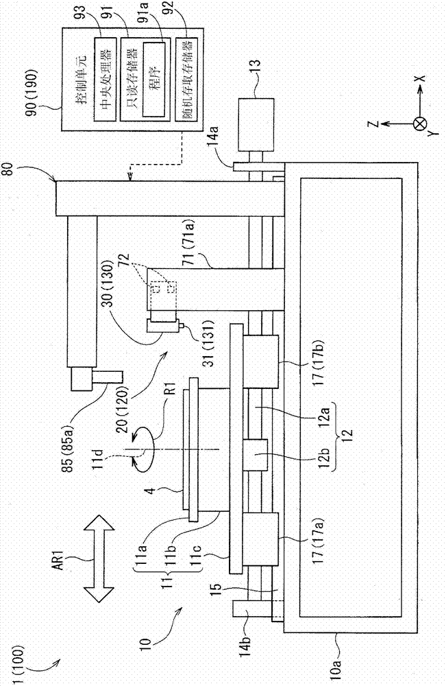
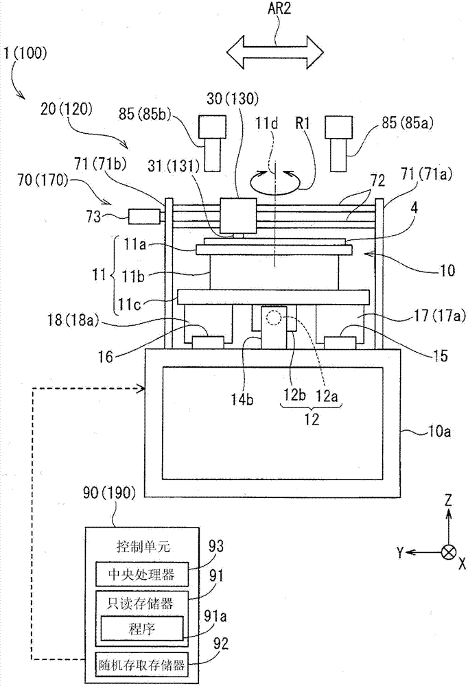
[0161] figure 1 and figure 2 These are a front view and a side view showing an example of the overall configuration of the scribing apparatus 1 in the first embodiment, respectively. The scribing device 1 is to draw a scribe line (cutting pattern) on the surface of a substrate (hereinafter, also simply referred to as "brittle material substrate") 4 formed of a brittle material such as a glass substrate or a ceramic substrate, etc. : device for longitudinal cracks).

[0162] Such as figure 1 and figure 2 As shown, the marking device 1 mainly includes a holding unit 10 , a marking unit 20 , an imaging unit 80 , and a control unit 90 . In addition, in figure 1 In each of the drawings and the following figures, in order to clarify the directional relationship of these members, an XYZ rectangular coordinate system with the Z-axis direction as the vertical direction and the XY plane as the horizontal plane is appropriately indicated as needed.

[0163] Here, in th...

no. 2 Embodiment approach

[0263] Next, a second embodiment of the present invention will be described. The scribing apparatuses 1 and 100 of the first and second embodiments have the same configuration except that the configurations of the corresponding scribing units 20 and 120 are different from each other. Therefore, the following description will focus on this difference.

[0264] In addition, the same reference numerals are given to the same components in the scribing apparatus 1, 100, and the components with the same reference numbers have already been described in the first embodiment. Therefore, descriptions of components corresponding to the same symbols are omitted below.

[0265]

[0266] Figure 10 and Figure 11 It is a front view and a bottom view showing an example of the configuration in the vicinity of the scribe wheel 160 . Figure 12 is a bottom view used to illustrate the caster stabilization effect of the kingpin. Below, refer to figure 1 , figure 2 ,and Figure 10 to Fi...

Embodiment 1 and comparative example 1

[0316] Figure 16 is a diagram for explaining a test method for evaluating the end face strength of the scored brittle material substrate 4 .

[0317] Figure 17 It is a figure which shows the test conditions of Example 1 and Comparative Example 1. Figure 18 It is a graph showing the test results of Example 1 and Comparative Example 1. Figure 19 It is the blade portion 61 having a rounded surface 67 of Embodiment 1 (refer to Figure 7 ) Photograph of a scribed brittle material substrate 4. Figure 20 It is the blade of Comparative Example 1 that does not have a rounded surface (refer to Figure 9 ) Photograph of a scribed brittle material substrate 4.

[0318] In Example 1 and Comparative Example 1, a 4-point bending test was employed as a test for evaluating the end surface strength of the scored brittle material substrate 4 . Such as Figure 16 and Figure 17 As shown, in this test, the distance D1 between the upper fulcrums 95 (95a, 95b) is 10.0mm, and the distanc...


PUM

PropertyMeasurementUnit
particle sizeaaaaaaaaaa

Abstract

The invention provides a marking method which can be used to form good marking on a substrate made of brittle material, and a diamond point, and further provides a marking device comprising the diamond point. The diamond point is a tool which forms marking on the substrate (4) made of brittle material by being moved relative to the substrate (4) made of brittle material. A blade part (61) of the diamond point is four-arris frustum-shaped, and mainly comprises a front end face (64), a plurality of (four in the present embodiment) bevels (65(65a-65d)), and a plurality of hollows (67(67a-67d)). Furthermore, each ridge (66) of the blade part (61) comprises a straight line (the intersecting line of two abutting bevels) part (68) and a curve part (69) which is located on the connected hollows (67) of the abutting bevels (65) and is connected with the straight line part (68) and the front end face (64).

Description

technical field [0001] The invention relates to a method for forming a scribe line on a brittle material substrate, a diamond tip used in the method, and a scribe device including the diamond tip. Background technique [0002] Conventionally, there is known a technique of cutting a glass substrate with a diamond tip or a scribing wheel to form scribe lines on the glass substrate (for example, Patent Document 1). [0003] [Background Art Document] [0004] [Patent Document] [0005] Patent Document 1: Japanese Patent Laid-Open No. 2010-085791 Contents of the invention [0006] [Problem to be Solved by the Invention] [0007] In the technology of Patent Document 1, there is a problem that chips are generated near the scribe line due to cutting of the glass substrate. Furthermore, in the technique of Patent Document 1, there may be a problem that microcracks (fine cracks) are generated in the scribed cross section in some cases. [0008] Therefore, the object of the pres...

Claims


Application Information

Patent Timeline
Patent Type & Authority Patents(China)
IPC IPC(8): C03B33/02C03B33/10
CPCB28D5/04C03B33/033C03B33/037C03B33/10Y02P40/57
Inventor 福西利夫千代康弘山本幸司中野忠信北市充
Owner MITSUBOSHI DIAMOND IND CO LTD
Why Eureka
Try Eureka