Upper cam mechanism of computerized flat knitting machine

A computerized flat knitting machine and needle groove technology, which is applied in knitting, weft knitting, textiles and papermaking, etc. It can solve the problems of large vibration, stitch damage, and single needle protection structure on the needle selection, so as to prolong the service life and reduce the Effect of vibration amplitude and unplanned displacement

Active Publication Date: 2013-12-25
NINGBO CIXING
View PDF6 Cites 0 Cited by
  • Summary
  • Abstract
  • Description
  • Claims
  • Application Information

AI Technical Summary

Problems solved by technology

[0003] The existing needle selection upper guard has a single structure, and most of them adopt a right-angle structure, that is, the sides of each turning point of the needle selection upper guard are perpendicular to the bottom edge
Although this type of upper guard is simple to manufacture, because the needle track provided by this type of upper guard requires the stitches to turn at right angles frequently, the movement process of the needle selection is not stable enough, and the vibration is large, which may easily cause damage to the stitches or other parts.

Method used


Image

  • Upper cam mechanism of computerized flat knitting machine
  • Upper cam mechanism of computerized flat knitting machine
  • Upper cam mechanism of computerized flat knitting machine

Examples


Embodiment 1

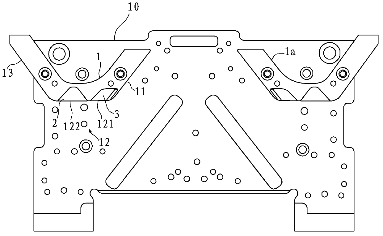
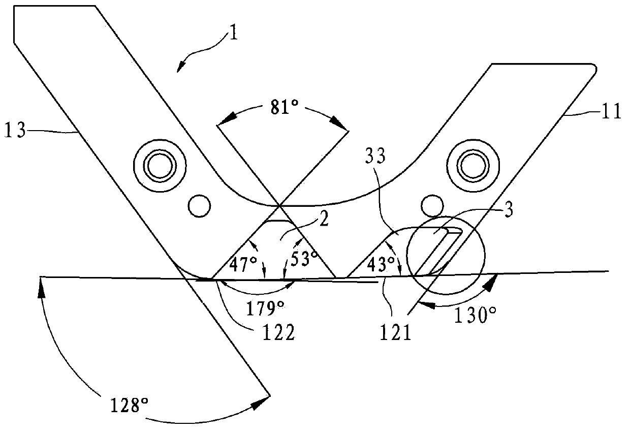
[0024] Example 1, such as figure 1 and figure 2 As shown, the upper guard mechanism in this embodiment is used in a single system, specifically, it includes a motherboard 10 and an upper left guard 1 and an upper right guard 1a arranged side by side on the motherboard 10 at intervals, an upper left guard 1 and an upper left guard 1a. The upper right bezel 1a is mirror-symmetrical with the central axis of the motherboard 10 as the symmetry line, and the upper left bezel 1 and the upper right bezel 1a are mirror-symmetric pieces. The upper left guard hill 1 includes the first section of needle surface 11, the second section of needle surface 12 and the third section of needle surface 13 in sequence, the first section of needle surface 11 and the third section of needle surface 13 are connected with the second section of needle surface. The needle surfaces 12 are connected by circular arc transitions, and the first section of the needle surface 11 and the third section of the n...

Embodiment 2

[0027] Example 2, such as Figure 4 and Figure 5 As shown, the upper guard mechanism in this embodiment is used in a dual system, specifically, the upper left guard 1, the middle upper guard 4, the upper right guard 1a, and the upper left guard 1 are arranged side by side on the motherboard 10 at intervals. It is mirror-symmetrical with the upper right guard mountain 1a taking the central axis of the motherboard 10 as the line of symmetry.

[0028] The middle and upper mountain guard 4 is located between the upper left guard hill 1 and the upper right guard hill 1a. The middle and upper hill guard 4 is a left-right symmetrical piece with the center line as the axis of symmetry. The second-level movement surface 42 and the third-level movement surface 43, the first-level movement surface 41, the third-level movement surface 43 and the second-level movement surface 42 are all arc transition connections, and the first-level movement surface 41 and The third-level needle surfac...

Embodiment 3

[0032] Example 3, such as Figure 6 As shown, the upper guard mechanism in this embodiment is used in the three systems, and two middle and upper guard hills 4 are arranged between the left upper guard 1 and the right upper guard 1a. Refer to Example 2 for other structures.


PUM


Abstract

An upper cam mechanism of a computerized flat knitting machine comprises a motherboard and at least two upper cams arranged on the upper end face of the motherboard. Each upper cam sequentially comprises a first-section needle moving surface, a second-section needle moving surface and a third-section needle moving surface, each first-section needle moving surface and each third-section needle moving surface are both in circular arc transition with the corresponding second-section needle moving surface and extend upward to stretch bilaterally with the corresponding second-section needle moving surface serving as a start end, each second-section needle moving surface recesses to form needle moving grooves, and needle inlet sections of the needle moving grooves are in oblique plane transition. The needle moving grooves with oblique needle inlet sections are additionally arranged on the horizontal needle moving surfaces of the upper cams, and accordingly stable transition of needle feet can be guaranteed, vibration amplitude and unplanned displacement are effectively reduced, butts of long needles are protected, accidental striking of the needle butts is prevented, and further the service life of the needles is prolonged.

Description

technical field [0001] The invention relates to a component of a computerized flat knitting machine, in particular to an upper mountain protection mechanism, which belongs to the technical field of knitting equipment. Background technique [0002] The needle selection upper guard of the computerized flat knitting machine is mainly used to determine the movement track of the stitches during needle selection. Specifically, during the knitting process, the upper stitches of the long needles are sent to the track of the transfer triangle, and after the transfer is completed, Return the upper stitch of the long needle. During the movement, the speed is required to be stable, the path is smooth, and there should be no large vibration or sudden unplanned displacement. [0003] The existing needle selection upper guard has a single structure, and mostly adopts a right-angle structure, that is, the sides of each turning point of the needle selection upper guard are perpendicular to ...

Claims


Application Information

Patent Timeline
Patent Type & Authority Patents(China)
IPC IPC(8): D04B15/36
Inventor 孙平范
Owner NINGBO CIXING
Why Eureka
Try Eureka