Water draining and flushing mechanism

一种排水阀、止水的技术,应用在带水箱的冲洗设备、供水装置、薄料处理等方向,能够解决冲刷系统与坐便器配合设计限制、结构体积大、组装及维修复杂等问题,达到冲刷功能容易保证、尺寸减小、拓宽设计空间的效果

Active Publication Date: 2012-12-05
XIAMEN AXENT
View PDF8 Cites 28 Cited by
  • Summary
  • Abstract
  • Description
  • Claims
  • Application Information

AI Technical Summary

Problems solved by technology

[0004] Adopting the structure described in the above-mentioned invention patent, although the desired effect can be achieved, the above-mentioned technical solution has higher requirements on the parts of the drain valve, and stricter requirements on the installation position, and the structure itself is relatively large in size, and the assembly and maintenance are relatively complicated.
Therefore, there are more restrictions on the matching design of the flushing system and the toilet

Method used


Image

  • Water draining and flushing mechanism
  • Water draining and flushing mechanism
  • Water draining and flushing mechanism

Examples


Embodiment 1

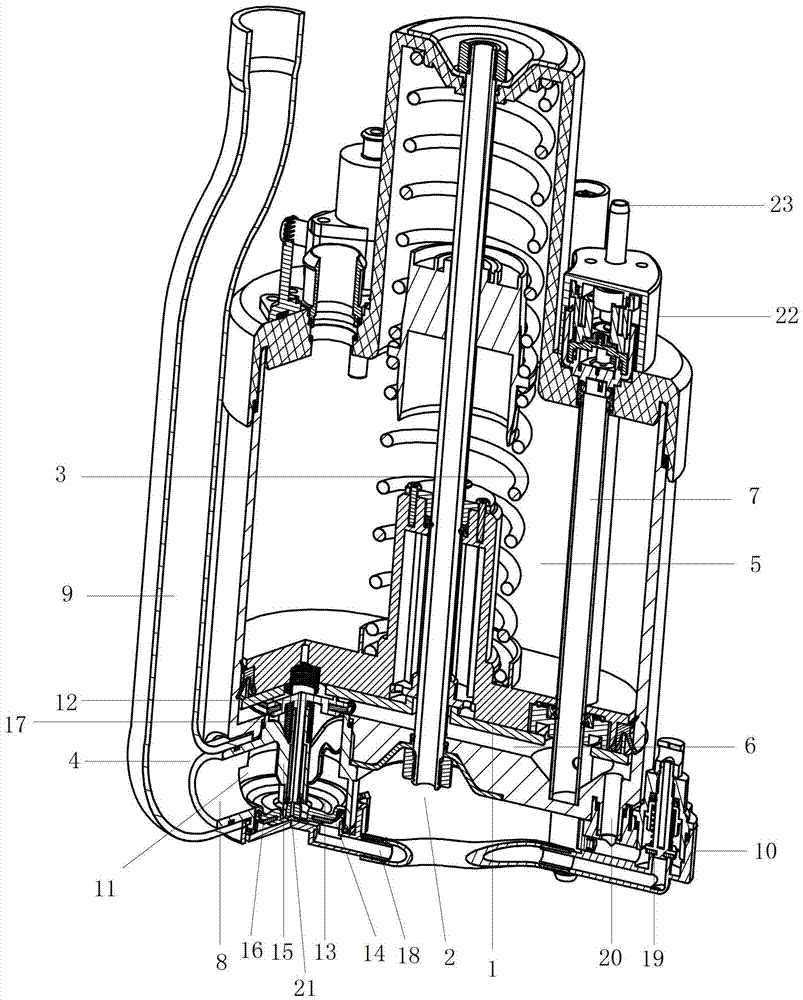
[0047] as attached figure 1 , 2 As shown, the external water source is connected to the water inlet joint 26 on the water inlet control assembly 22 . A part of water replenishes water to the toilet through the replenishment channel 23 of the water inlet and stop water control assembly 22, and another part of water enters the lower box body 6 through the water inlet pipe 7 through the inner cavity of the water inlet and stop water control assembly 22.

[0048] When using for the first time, the inlet of drain valve 4 is closed naturally. Now the water pressure acts on the drain valve 4 water-stop seal 12, the water-stop seal 12 seals the inlet of the drain valve 4, and the water is accumulated in the casing. Due to the effect of water pressure, the first piston 1 moves upward against the pressure of the main energy storage spring 3 . When the first piston 1 moves to a preset position, the first piston 1 pushes the travel switch 24 on the water stop control assembly 22 to clo...

Embodiment 2

[0054] The drain valve 4 of this embodiment is different from that of Embodiment 1, and the rest are basically the same.

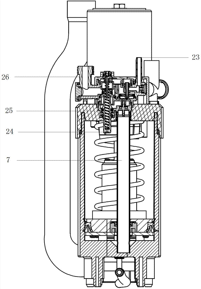
[0055] as attached figure 1 , 2 , 3, the external water source is connected to the water inlet connector 26 on the water inlet control assembly 22 . A part of water replenishes water to the toilet through the replenishment channel 23 of the water inlet and stop water control assembly 22, and another part of water enters the lower box body 6 through the inner cavity of the water inlet and stop water control assembly 22 through the water inlet conduit.

[0056] When using for the first time, the drain valve 4 inlets are naturally closed. Now the water pressure acts on the drain valve 4 water-stop seal 12, the water-stop seal 12 seals the inlet of the drain valve 4, and the water is accumulated in the casing. Due to the effect of water pressure, the first piston 1 moves upward against the pressure of the main energy storage spring 3 . When the first pisto...

Embodiment 3

[0062] The water-tight seal 12 of this embodiment is different from that of Embodiment 1, and the rest are basically the same.

[0063] (The water-stop seal 12 shown here rotates around a fixed axis).

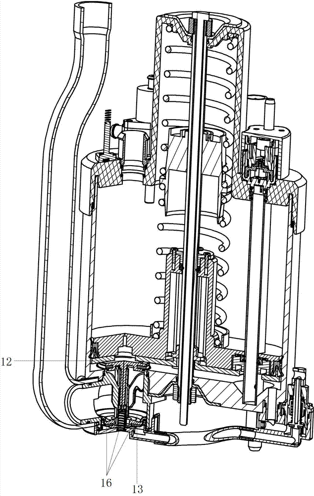
[0064] Such as figure 1 , 2 , 4 and 5, the external water source is connected to the water inlet connector 26 on the water inlet control assembly 22 . A part of water replenishes water to the toilet through the replenishment channel 23 of the water inlet and stop water control assembly 22, and another part of water enters the lower box body 6 through the inner cavity of the water inlet and stop water control assembly 22 through the water inlet conduit.

[0065] When using for the first time, the drain valve 4 inlets are naturally closed. Now the water pressure acts on the drain valve 4 water-stop seal 12, the water-stop seal 12 seals the inlet of the drain valve 4, and the water is accumulated in the casing. Due to the effect of water pressure, the first piston 1 moves upwa...


PUM


Abstract

The invention relates to a water draining and flushing mechanism, which comprises a box body, a first piston, a fixing rod used for mounting the first piston, a main energy storage spring and a water draining valve, wherein the first piston is mounted in the box body and divides the box body into an upper box body and a lower box body; the lower box body is a water storage space formed by the first piston and the box body and positioned at the lower part of the box body; the main energy storage spring is mounted on the first piston and produces a force pointing at the direction of the lower box body over the first piston; a water inlet pipe is communicated with the lower box body; a mounting opening of the water draining valve is arranged on the bottom surface of the lower box body; the water draining valve is mounted at the outer part of the lower box body through the mounting opening of the water draining valve, is provided with at least a water draining opening used for being connected with a water flushing pipeline, and is connected with a water draining control component used for controlling the opening and the closing of the water draining valve. The water draining and flushing mechanism has the beneficial effects that requirements for the volume and the position of the flushing mechanism is reduced, so that the whole toilet or other sanitary ware can be designed individually on a small scale and all components are very easy to mount, replace and repair.

Description

technical field [0001] The invention relates to a drainage mechanism, more specifically, to a drainage and flushing mechanism, which is used in the bathroom field such as a toilet, and plays the role of drainage and flushing. Background technique [0002] On the basis of ensuring performance, in order to reduce the volume of the toilet and make the shape of the toilet more beautiful, it is necessary to achieve a large enough flushing capacity in the smallest possible volume. [0003] Chinese invention patent application number ZL 201010252463.9 discloses a flushing mechanism, including a tank; a water outlet is opened around an axis on the bottom of the tank; a guide rod is fixed axially relative to the tank along the axis; The first piston that seals and slides on the cylindrical inner surface and the guide rod in the axial direction at the same time; the first piston that is installed in the upper chamber around the guide rod is loaded with a spring; and can seal and slide...

Claims


Application Information

Patent Timeline
Patent Type & Authority Applications(China)
IPC IPC(8): E03D3/04E03D1/34
CPCE03D3/04Y10T137/7287
Inventor 许海涛吴爱民
Owner XIAMEN AXENT
Why Eureka
Try Eureka