Regulator for micro-dose flow velocity and transfusion set thereof

A flow rate regulator and micro-dosing technology, applied in the field of infusion sets, can solve problems such as patient impact, and achieve the effects of avoiding misoperation, safe and reliable use, and convenient flow rate selection.

Inactive Publication Date: 2012-12-12
JIANGSU ASIALAND BIO MED TECH
View PDF5 Cites 8 Cited by
  • Summary
  • Abstract
  • Description
  • Claims
  • Application Information

AI Technical Summary

Problems solved by technology

However, the regulator is roughly cylindrical, and the flow rate is selected by rotation. The cylinder is marked with a marking line. When selecting, the scale value aligned with the marking line is the flow rate at this position. The maximum flow rate value of the regulator is due to the full open position reserved for the ventilation test of the pipeline during production, and this full open position is located at the extension of the 250ml / h position, and it can be opened to the full position if you are not careful during operation. In the open position, the instantaneous flow rate reaches from 250ml / h to 2500ml / h, which is very likely to cause irreparable impact on the patient

Method used


Image

  • Regulator for micro-dose flow velocity and transfusion set thereof
  • Regulator for micro-dose flow velocity and transfusion set thereof
  • Regulator for micro-dose flow velocity and transfusion set thereof

Examples


Embodiment Construction

[0021] The present invention is described in further detail now in conjunction with accompanying drawing. These drawings are all simplified schematic diagrams, which only illustrate the basic structure of the present invention in a schematic manner, so they only show the configurations related to the present invention.

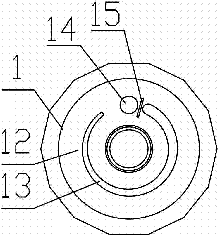
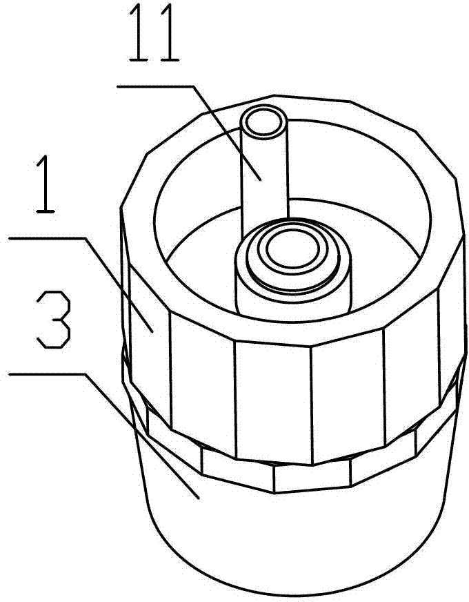
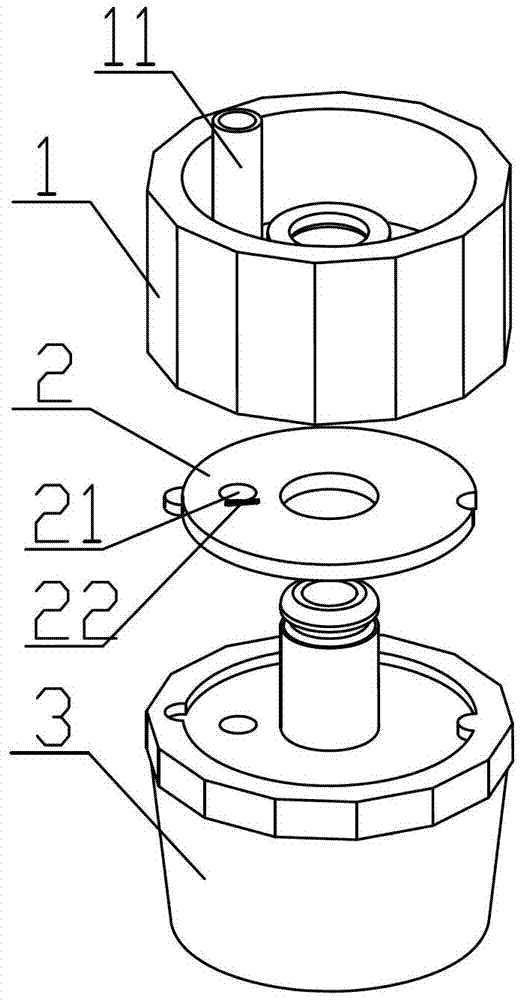
[0022] Such as Figure 1-7 As shown, the best embodiment of the micro-dosage flow rate regulator of the present invention includes an upper housing 1, a core 2 and a lower housing 3, the upper housing 1 and the lower housing 3 are rotatably connected, and the core 2 is located at In the closed cavity formed by the upper casing 1 and the lower casing 3, the upper casing 1 is provided with a liquid inlet pipe 11, and the upper casing 1 is located below the liquid inlet pipe 11 and has a retaining ring 12, and the retaining ring 12 is provided with a There is an annular groove 13 whose aperture diameter gradually becomes larger from the beginning to the end. The...


PUM


Abstract

The invention relates to a regulator for micro-dose flow velocity, comprising an upper shell body, a core body and a low shell body. A liquid inlet pipe is arranged on the upper shell body; a retaining ring is arranged below the liquid inlet pipe on the upper shell body; a ring groove, the bore diameter of which increases gradually and the head and the tail of which are not communicated, is formed in the retaining ring; a liquid passing hole is formed in the core body; communication or closing between the liquid passing hole and the ring groove is realized by the mutual rotation of the upper shell body and the lower shell body; a liquid outlet pipe which is communicated with the liquid passing hole is arranged on the lower shell body; the cross section of the upper shell body is regular polygon; the outer ring at the lower shell body, which is contacted with the upper shell body, is regular polygon which fits the upper shell body; reticule is marked on the upper shell body; and corresponding flow scale marks are marked on each side of the regular polygon of the lower shell body. The regulator can accurately control the flow velocity and avoid misoperation. Regular polygon is designed to be distributed according to the characteristics of flow velocity. When the upper shell body rotates and two regular polygons mutually fit, the flow velocity is the scale mark value corresponding to the reticule. The use is safer and more reliable.

Description

technical field [0001] The invention relates to the technical field of infusion sets, in particular to a micro-dosage flow rate regulator and the infusion set. Background technique [0002] The infusion set is mainly used for aseptic treatment of intravenous infusion, and it is a medical consumable that establishes a channel between the vein and the liquid medicine. It is generally composed of an intravenous needle, a protective cap, an infusion hose, a liquid medicine filter, a flow rate regulator, a drip pot, a cork puncturer, and an air inlet pipe air filter connection. [0003] For some special diseases, micro-dose injection is required. If the flow rate is not properly controlled, too fast or too slow will affect the patient's tolerance, especially after the speed is too fast, the patient's heart can't stand it, there will be pain, and even induce death. It has been reported In the United States, there was a case of death caused by improper control of the flow rate whe...

Claims


Application Information

Patent Timeline
Patent Type & Authority Applications(China)
IPC IPC(8): A61M5/175A61M5/14
Inventor 陶英亮毛力真
Owner JIANGSU ASIALAND BIO MED TECH
Why Eureka
Try Eureka