Supercharge Your Innovation With Domain-Expert AI Agents!

Hole distribution method and hole distribution device for circular structure

A ring-shaped structure and hole layout technology, which is applied in boring/drilling, drilling/drilling equipment, and drilling templates for workpieces, can solve problems such as inability to machine ring-shaped structures, and achieve mechanical processing inconvenient effect

Active Publication Date: 2015-06-10
WUHAN MARINE MACHINERY PLANT
View PDF6 Cites 0 Cited by
  • Summary
  • Abstract
  • Description
  • Claims
  • Application Information

AI Technical Summary

Problems solved by technology

[0005] In order to solve the problem that the existing technology cannot directly machine the annular structure beyond the scope of the CNC boring and milling machine to open holes on it, the embodiment of the present invention provides a method and device for arranging holes in the annular structure

Method used


Image

  • Hole distribution method and hole distribution device for circular structure
  • Hole distribution method and hole distribution device for circular structure
  • Hole distribution method and hole distribution device for circular structure

Examples


Embodiment 1

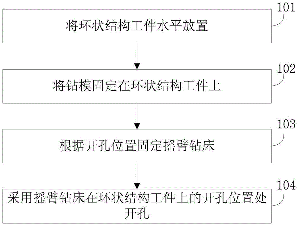
[0031] The embodiment of the present invention provides a ring structure hole layout method, see figure 1 , the method flow includes:

[0032] Step 101: Place the ring-shaped workpiece horizontally, and mark the opening position on the ring-shaped workpiece.

[0033] Step 102: Fix the drilling jig on the ring structure workpiece.

[0034] Adjust the drilling mold, place the drilling mold flat on the ring structure workpiece, align the center of the drill bush with the opening position, and spot weld the hollow pin to fix the drilling mold.

[0035] Step 103: Fix the radial drilling machine according to the opening position.

[0036] Specifically, place the radial drilling machine on the horizontal adjustment mechanism, adjust the level of the radial drilling machine with the four adjustment screws at the bottom of the horizontal adjustment mechanism, weld the compression plate to the horizontal adjustment mechanism after leveling, and lock the compression bolts on the nut. ...

Embodiment 2

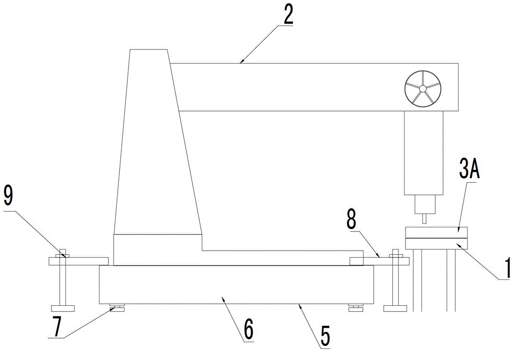
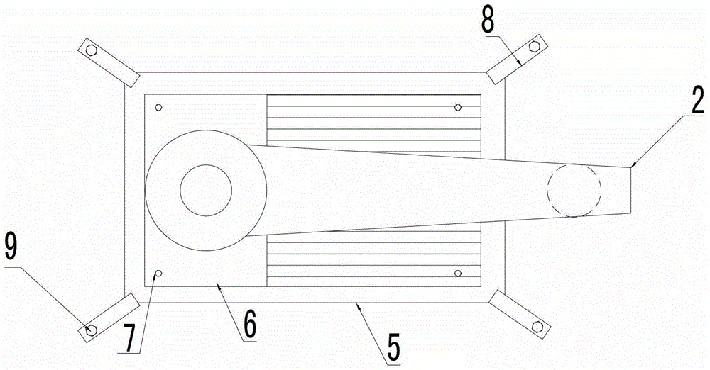
[0050] An embodiment of the present invention provides a device for distributing holes with a ring structure, see Figure 2-Figure 4, the device includes: a radial drilling machine 2 for drilling a ring structure workpiece 1, a drilling template 3 for guiding the radial drilling machine 2 to drill holes on the ring structure workpiece 1, and fixing the drilling template 3A on the ring The positioning structure on the workpiece 1 of the ring structure, and the opening position is marked on the workpiece 1 of the ring structure. When the device is in use, the drilling template 3A is fixed on the horizontally placed ring-shaped workpiece 1, and the radial drilling machine 2 is fixed according to the opening position to open the hole.

[0051] Further, the above-mentioned drilling template 3A is circular or arc-shaped, and the corresponding opening position on the drilling template 3A is provided with a drill bushing 3B, and the radius of the circle or arc passing through the cent...


PUM


Abstract

The invention discloses a hole distribution method and a hole distribution device for a circular structure; and the method and the device belong to the technical field of hole distribution. The method comprises that a work piece in a circular structure is placed horizontally, and hole positions are marked on the work piece in a circular structure; a drill mould is fixedly arranged on the work piece in the circular structure; a radial drilling machine is fixedly arranged according to the hole positions; and holes are arranged at the hole positions on the work piece in the circular structure by the radial drilling machine. The device comprises the radial drilling machine and the drill mould. According to the hole distribution method and the hole distribution device for the circular structure, the work piece in the circular structure is placed horizontally, the holes are arranged on the work piece in the circular structure by the radial drilling machine and the drill mould, so that not only is the problem that the mechanical processing of the holes is inconvenient due to the complicated vertical clamping of the work piece in the circular structure solved, but also the problem that the work piece in the circular structure is too large and cannot be processed on a numerical control boring machine is solved.

Description

technical field [0001] The invention relates to the technical field of hole arrangement, in particular to a method and device for hole arrangement in a ring structure. Background technique [0002] Pintooth transmission is a special form of gear transmission, mainly used in low-speed large and medium-sized mechanical equipment; pintooth transmission includes gears and pin wheels. In the traditional pin wheel machining method, the pin hole frame is usually designed as a separate component. After the pin hole pitch circle line and the opening position are marked, the pin hole frame is mounted on the CNC boring machine by vertical clamping method, and the Machined hole. [0003] In the process of realizing the present invention, the inventor finds that there are at least the following problems in the prior art: [0004] For the pin tooth transmission structure of large and medium-sized equipment, due to the large number of pin holes and the large pitch circle of the pin hole ...

Claims


Application Information

Patent Timeline
IPC IPC(8): B23B41/02B23B47/28
Inventor 陈蓓张雷彭浩张勇勇孙文杰
Owner WUHAN MARINE MACHINERY PLANT
Features
  • R&D
  • Intellectual Property
  • Life Sciences
  • Materials
  • Tech Scout
  • Unparalleled Data Quality
  • Higher Quality Content
  • 60% Fewer Hallucinations
Learn More