Mechanism for checking feeder

The technology of a feeder and a connecting rod, which is applied to the mechanism of the feeder and the mechanism of the consignment feeder, can solve the problems of complex structure, easy damage and high cost, and achieve the effect of overcoming the complex structure

Inactive Publication Date: 2012-12-12
戚继华
View PDF0 Cites 0 Cited by
  • Summary
  • Abstract
  • Description
  • Claims
  • Application Information

AI Technical Summary

Problems solved by technology

[0005] Beneficial effects: the present invention adopts the above scheme, effectively overcomes the defects of complex structure, low precision, high cost, easy damage and poor versatility existing in the existing feeding equipment

Method used


Image

  • Mechanism for checking feeder

Examples


Embodiment Construction

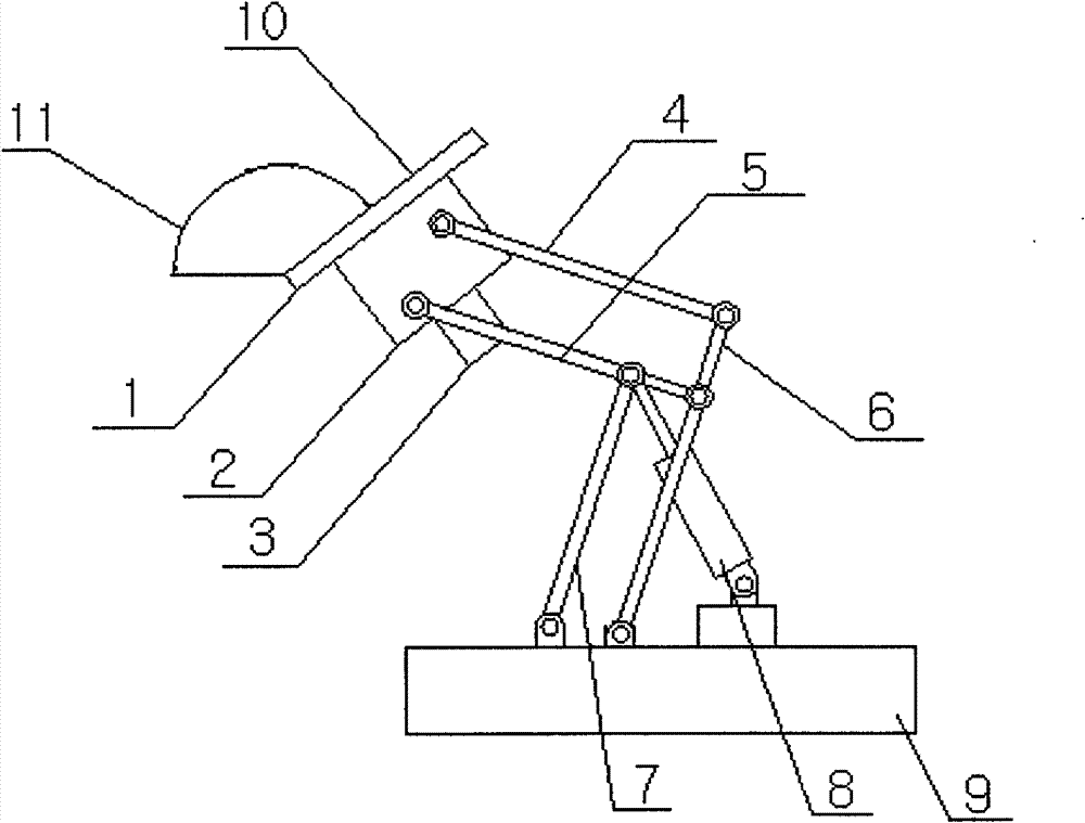
[0008] The consignment conveyor has a single-action connecting rod 4, and the single-acting connecting rod 4, double-acting connecting rod 5, automatic connecting rod 6, and single- and double-acting connecting rod 7 are hinged at corresponding positions with pins, and at the same time, the pins are used to connect the electromagnetic Suction cup 1, reducer 2, and stepping motor 3 form a unified whole hinged on one end of single-acting connecting rod 4 and double-acting connecting rod 5, and the other end of automatic connecting rod 6 and single-double acting connecting rod 7 is hinged on the fixed table , the above-mentioned parts form a parallelogram luffing mechanism, and the piston cylinder of the cylinder 8 is integrally hinged with the fixed table 9, the upper mold 10 and the lower mold 11.


PUM


Abstract

The invention discloses a mechanism for checking a feeder. A single-acting connection rod, a double-acting connection rod, an automatic connection rod and a single and double-acting connection rod are hinged at corresponding parts through pins, a unified whole formed by an electromagnetic sucking disc, a reducer and a stepping motor is hinged on one end of each of the single-acting connection rod and the double-acting connection rod through the pins at the same time, and the other end of each of the automatic connection rod and the single and double-acting connection rod is hinged on a fixing table. A piston cylinder of a gas cylinder, the fixing table, an upper mould and a lower mould are integrally hinged through a parallelogram luffing mechanism formed by the parts.

Description

technical field [0001] The invention relates to a mechanism of a feeder, in particular to a mechanism of a consignment conveyor. The invention belongs to the field of stamping technology and the field of automation technology. Background technique [0002] At present: although the existing feeding equipment is flexible and convenient to send the raw materials to the designated position of the positional machine tool, the feeding equipment mechanism is not only complicated in structure, low in precision and high in cost, but also easy to be damaged due to the complex structure, especially , this mechanism has poor versatility. Contents of the invention [0003] The object of the present invention is to provide a mechanism for a consignment conveyor, which overcomes the defects of complex structure, low precision, high cost, easy damage and poor versatility of the above mechanism. [0004] The technical solution adopted by the present invention to solve the technical probl...

Claims


Application Information

Patent Timeline
Patent Type & Authority Applications(China)
IPC IPC(8): B30B15/30
Inventor 戚继华
Owner 戚继华
Why Eureka
Try Eureka