Low-temperature ball valve

A ball valve and low-temperature technology, applied in the direction of valve devices, cocks including cut-off devices, engine components, etc., can solve the problems of dangerous gas polluting the environment and high manufacturing costs, and achieve reliable sealing at room temperature and low temperature, low manufacturing costs, and avoid abnormal rise pressure risk effect

Active Publication Date: 2012-12-12
NEWAY VALVE SUZHOU
View PDF8 Cites 5 Cited by
  • Summary
  • Abstract
  • Description
  • Claims
  • Application Information

AI Technical Summary

Problems solved by technology

[0006] For this reason, the technical problem to be solved by the present invention is that the pressure relief channel in the prior art cryogenic ball valve releases the dangerous ga

Method used


Image

  • Low-temperature ball valve
  • Low-temperature ball valve
  • Low-temperature ball valve

Examples


Embodiment 1

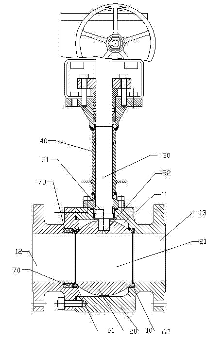
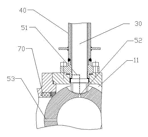
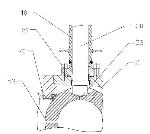
[0035] figure 1 Shown is the cryogenic ball valve described in this embodiment, including a valve body 10, a spherical valve core 20, a valve stem 30, and a tubular support 40, wherein,

[0036] The valve body 10 has an inlet 12 and an outlet 13, and a cavity 11 is formed in the valve body 10, and the cavity 11 communicates with the inlet 12 and the outlet 13;

[0037]The spherical valve core 20 is placed in the cavity 11 and the outlet side of the valve body 10 is in sealing fit with the side wall of the cavity 11. In this embodiment, the valve core 20 is located in the valve body 10, the outlet side of the cavity 11 is sealed with the side wall of the cavity 11 as an outlet end seal 62 arranged between the side wall and the valve core 20, and the outlet end seal 62 is in the shape of a smooth tube seals, such as Figure 4 As shown, the tubular sealing ring is placed in the annular groove 14 provided at the outlet end of the valve body 10, and the structure of the annular g...

Embodiment 2

[0044] The cryogenic ball valve described in this embodiment includes a valve body 10, a spherical valve core 20, a valve stem 30, and a tubular bracket 40, wherein,

[0045] The valve body 10 has an inlet 12 and an outlet 13, and a cavity 11 is formed in the valve body 10, and the cavity 11 communicates with the inlet 12 and the outlet 13;

[0046] The spherical valve core 20 is placed in the cavity 11 and the valve body 10 is in sealing fit with the side wall of the cavity 11, and a through hole 21 is formed along its center line, which can be wound around the center line perpendicular to the center line. In this embodiment, the spool 20 is set to be located on the side wall of the valve body 10 and the cavity 11 to seal the inlet end between the side wall and the spool 20. 61 and the outlet end seal 62; the inlet end seal 61 and the outlet end seal 62 in this embodiment are the same, that is, the inlet end seal 61 and the outlet end seal 62 are both cylindrical and smooth ...


PUM


Abstract

A low-temperature ball valve comprises a valve body (10), a ball spool (20) and a valve rod (30). Axis of the valve rod (30) is coaxial with a rotary axis of the spool (20) and is fixedly connected with the spool (20). One end of a tubular support (40) is fixed on the valve body (10) and coaxially sleeved on the valve rod (30) to support the valve rod (30). A gap is reserved between the valve rod (30) and the tubular support (40). A decompression passage for communicating the gap with a through hole (21) is further arranged. In the prior art, the decompression passages of the low-temperature ball valves discharges hazardous gases during decompression and is high in cost. The low-temperature ball valve is environment-friendly and low in cost.

Description

technical field [0001] The invention relates to a ball valve, in particular to a low temperature ball valve. Background technique [0002] The ball valve has the action of rotating 90 degrees. The outer contour of the valve core is a sphere with a circular through hole or channel passing through its axis. The ball valve is mainly used to cut off, distribute and change the flow direction of the medium in the pipeline. It only needs to be rotated 90 degrees and a small rotational torque can be closed tightly. Cryogenic ball valves are mainly used in harsh environments where low-temperature media such as liquefied natural gas, liquid ethylene, and liquid oxygen are transmitted. [0003] Generally, a cryogenic ball valve includes a valve body, a valve core arranged in a valve seat, the valve core is a ball, a valve stem connected to the ball, supporting the valve stem, and a connecting pipe coaxially socketed with the valve stem. Since the low temperature ball valve is suitabl...

Claims


Application Information

Patent Timeline
IPC IPC(8): F16K5/08F16K5/20
Inventor 王国军王建华高开科王胜利
Owner NEWAY VALVE SUZHOU
Why Eureka
Try Eureka