Low-temperature ball valve
A ball valve, low temperature technology, used in valve devices, cocks including cut-off devices, engine components, etc., can solve the problems of dangerous gas pollution and high manufacturing costs, achieve reliable sealing at room temperature and low temperature, low manufacturing costs, and avoid abnormal rises. The effect of the risk of stress
- Summary
- Abstract
- Description
- Claims
- Application Information
AI Technical Summary
Problems solved by technology
Method used
Image
Examples
Embodiment 1
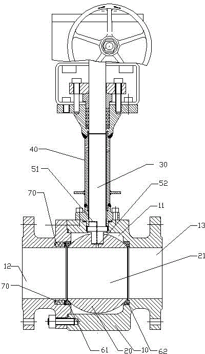
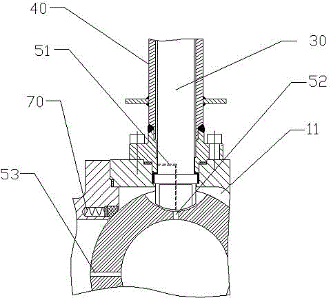
[0035] figure 1 Shown is the cryogenic ball valve described in this embodiment, including a valve body 10, a spherical valve core 20, a valve stem 30, and a tubular support 40, wherein,
[0036] The valve body 10 has an inlet 12 and an outlet 13, and a cavity 11 is formed in the valve body 10, and the cavity 11 communicates with the inlet 12 and the outlet 13;
[0037]The spherical valve core 20 is placed in the cavity 11 and the outlet side of the valve body 10 is in sealing fit with the side wall of the cavity 11. In this embodiment, the valve core 20 is located in the valve body 10, the outlet side of the cavity 11 is sealed with the side wall of the cavity 11 as an outlet end seal 62 arranged between the side wall and the valve core 20, and the outlet end seal 62 is in the shape of a smooth tube seals, such as Figure 4 As shown, the tubular sealing ring is placed in the annular groove 14 provided at the outlet end of the valve body 10, and the structure of the annular g...
Embodiment 2
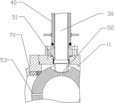
[0044] The cryogenic ball valve described in this embodiment includes a valve body 10, a spherical valve core 20, a valve stem 30, and a tubular bracket 40, wherein,
[0045] The valve body 10 has an inlet 12 and an outlet 13, and a cavity 11 is formed in the valve body 10, and the cavity 11 communicates with the inlet 12 and the outlet 13;
[0046] The spherical valve core 20 is placed in the cavity 11 and the valve body 10 is in sealing fit with the side wall of the cavity 11, and a through hole 21 is formed along its center line, which can be wound around the center line perpendicular to the center line. In this embodiment, the spool 20 is set to be located on the side wall of the valve body 10 and the cavity 11 to seal the inlet end between the side wall and the spool 20. 61 and the outlet end seal 62; the inlet end seal 61 and the outlet end seal 62 in this embodiment are the same, that is, the inlet end seal 61 and the outlet end seal 62 are both cylindrical and smooth ...
PUM
 Abstract
Description
Claims
Application Information
 - R&D
- Intellectual Property
- Life Sciences
- Materials
- Tech Scout
- Unparalleled Data Quality
- Higher Quality Content
- 60% Fewer Hallucinations
Browse by: Latest US Patents, China's latest patents, Technical Efficacy Thesaurus, Application Domain, Technology Topic, Popular Technical Reports.
© 2025 PatSnap. All rights reserved.Legal|Privacy policy|Modern Slavery Act Transparency Statement|Sitemap|About US| Contact US: help@patsnap.com


