Assistance type pin type back-pressure control method and back-pressure valve thereof
A back pressure valve and power-assisted technology, applied in valve details, safety valves, balance valves, etc., can solve the problems of high experimental cost, high diaphragm replacement rate, high diaphragm material requirements, and achieve enhanced operational stability and control high precision effect
- Summary
- Abstract
- Description
- Claims
- Application Information
AI Technical Summary
Problems solved by technology
Method used
Image

Examples
Embodiment approach 1
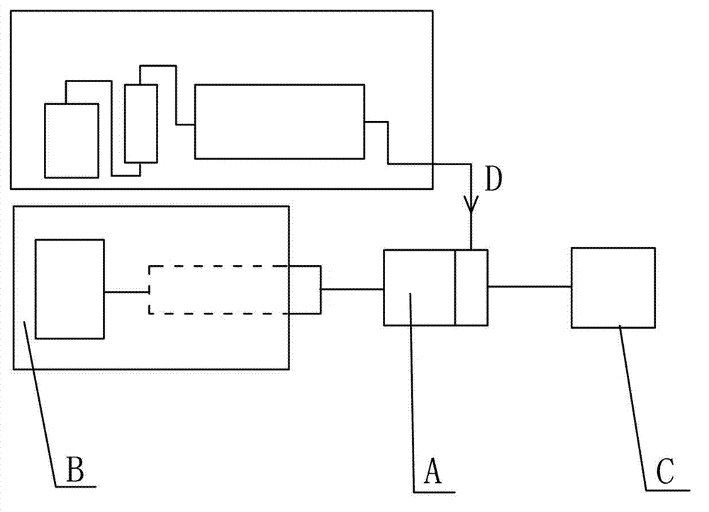
[0030] For the flow chart of the back pressure control system in the displacement experiment, see figure 1 As shown, the back pressure control system includes a back pressure valve A, a back pressure controller B and a gauge C. The back pressure valve A has a liquid inlet and a liquid outlet, the liquid outlet of the back pressure valve A is connected to the meter C, and the end of the back pressure valve A away from the liquid outlet is connected to the back pressure controller B. The fluid D generated during the displacement process enters the back pressure valve A through the liquid inlet; at this time, the back pressure controller B adjusts according to the difference between the set value and the output fluid pressure. The fluid enters the meter C along the liquid outlet; when the fluid pressure is lower than the set value, the controller pressurizes and the passage is disconnected.
[0031] Wherein, the back pressure controller B includes a pressure sensor, a micro plun...
Embodiment approach 2
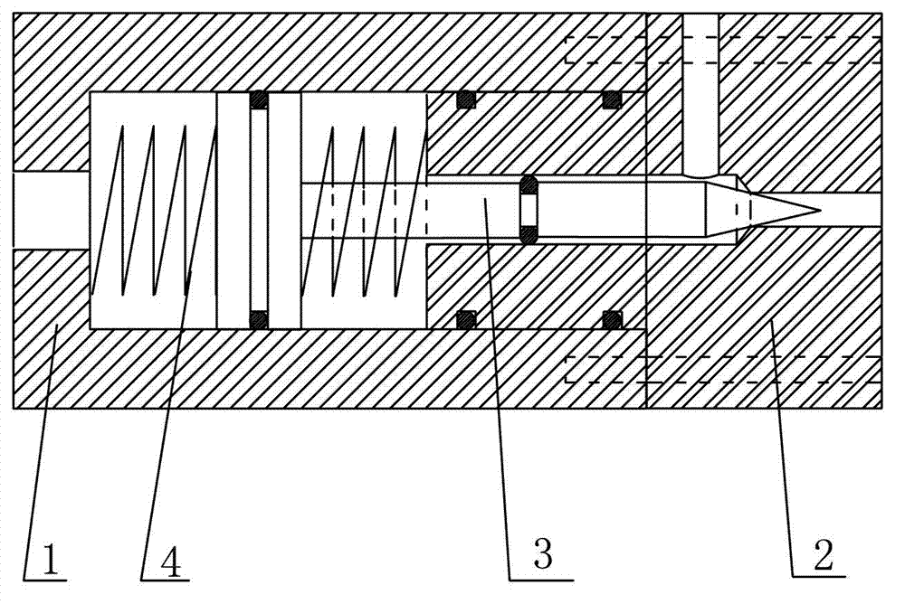
[0042] Such as Figure 2 to Figure 7 As shown, the embodiment of the present invention proposes a power-assisted needle-type back pressure control method, which includes the following steps:
[0043] A. Provide the back pressure valve A in the above embodiment;
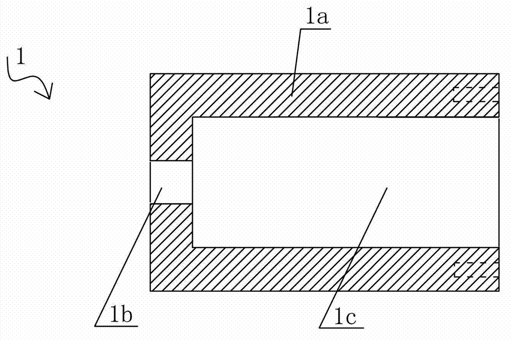
[0044] B. Connect the back pressure controller B to the back pressure valve A through the interface 1b of the back pressure valve A, and set the back pressure setting value on the back pressure controller B;
[0045] C. The fluid produced in the displacement process is injected into the right side of the piston 3a of the back pressure valve through the liquid inlet 2c;
[0046] D. The back pressure controller B is adjusted according to the difference between the set value and the pressure of the injected fluid. If the injected fluid pressure is higher than the set value, the two sides of the piston 3a are affected by the pressure difference and the auxiliary action of the spring. The needle plug 3 retreats (that is,...
PUM
 Abstract
Description
Claims
Application Information
 - Generate Ideas
- Intellectual Property
- Life Sciences
- Materials
- Tech Scout
- Unparalleled Data Quality
- Higher Quality Content
- 60% Fewer Hallucinations
Browse by: Latest US Patents, China's latest patents, Technical Efficacy Thesaurus, Application Domain, Technology Topic, Popular Technical Reports.
© 2025 PatSnap. All rights reserved.Legal|Privacy policy|Modern Slavery Act Transparency Statement|Sitemap|About US| Contact US: help@patsnap.com