A Measuring Method for Flight Parameters of Small Ducted Aircraft

A technology of flight parameters and measurement methods, applied in measurement devices, instruments, etc., can solve the problems of difficult flight parameters, errors, unreasonable design of the overall structure and control system, etc., to avoid coupling effects and improve accuracy.

Inactive Publication Date: 2014-10-08
BEIJING INSTITUTE OF TECHNOLOGYGY
View PDF5 Cites 0 Cited by
  • Summary
  • Abstract
  • Description
  • Claims
  • Application Information

AI Technical Summary

Problems solved by technology

When it is necessary to measure the aerodynamic parameters of the aircraft, the traditional method is to use sensors to measure each part of the small ducted aircraft and obtain the measurement data. Therefore, there will be a large error when the integrated calculation of these individually measured data will lead to unreasonable design of the whole machine structure and control system
In addition, since the small ducted aircraft is a statically unstable system, it is impossible to manually control the flight of this type of aircraft, and it is difficult to directly obtain the flight parameters, so the aerodynamic parameters of the aircraft cannot be calculated by the commonly used parameter identification method
[0003] At present, there is no measurement method that can simultaneously measure the mass and the position of the center of mass, the thrust of the engine, the pitching moment, the rolling moment and the yaw moment of the small ducted aircraft.

Method used


Image

  • A Measuring Method for Flight Parameters of Small Ducted Aircraft
  • A Measuring Method for Flight Parameters of Small Ducted Aircraft
  • A Measuring Method for Flight Parameters of Small Ducted Aircraft

Examples


Embodiment Construction

[0045] The present invention will be described in detail below with reference to the accompanying drawings and examples.

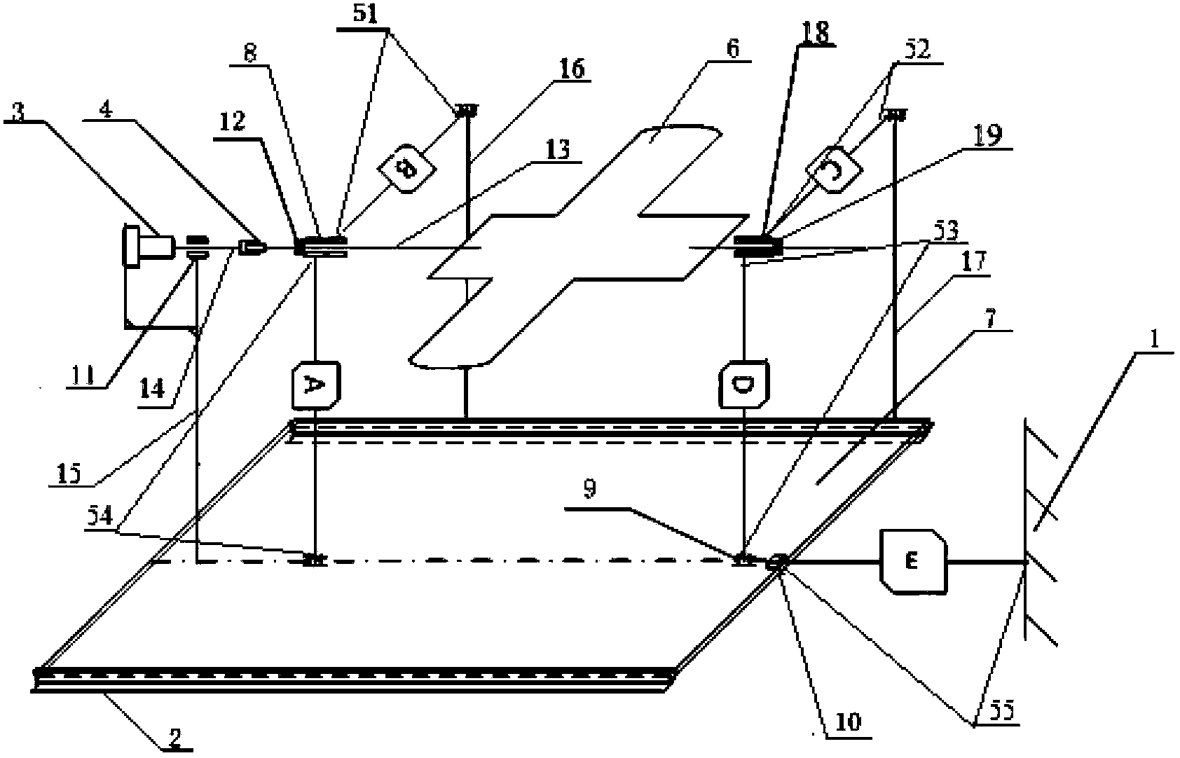
[0046] figure 1 Shows the schematic diagram of the internal connection of the system of the method provided by the present invention, the system includes a test platform seat 1, a linear guide rail 2, a torque sensor 3, a universal joint coupling 4, a small ducted aircraft 6, a workbench 7, the first A joint bearing 8, a hinge 9, a sliding bearing 10, an optical shaft support seat 11, a first axial limit ring 12, a fixed shaft 13, an optical shaft 14, steel rods 15~17, a second joint bearing 18, and a second shaft To the limit ring 19 and the tension-compression measuring devices 51-55, the tension-compression measuring devices are composed of tension-compression sensors connected with rigid shafts on both sides, and the two rigid shafts are coaxial.

[0047] The connection relationship between the various components in the system is:

[0048] Two parall...


PUM


Abstract

The invention discloses a measuring method for flight parameters of a small ducted aircraft. The method can realize the purpose of improving the measuring convenience and the accuracy of measured data. According to the method, sensors are orthogonally arranged according to the coordinate system of the body. The method comprises the steps of: arranging a torque sensor along the axis direction of a transverse body; in a vertical plane, connecting one ends of two pull pressure measuring devices with a fixed shaft of the transverse body respectively, and connecting the other ends of the two pull pressure measuring devices with a horizontal worktable, wherein the two devices are vertical; in a horizontal plane, connecting one ends of the pull pressure measuring devices with left and right axis of the transverse body respectively, and connecting the other ends of the pull pressure measuring devices with a hinge of a vertical steel rod of the horizontal worktable, wherein the two devices are horizontal; the torque sensor is connected with the aircraft through a universal coupler and the pull pressure sensor is connected with the aircraft through a joint bearing. Measurement of quality and location of the center of mass of the small ducted aircraft, thrust of the engine, pitching moment, rolling moment and yawing moment is realized.

Description

technical field [0001] The invention belongs to the field of measurement system design, and in particular relates to a method for measuring flight parameters of a small ducted aircraft. Background technique [0002] At present, small ducted aircraft is becoming one of the key objects of UAV research at home and abroad. The structure and control system design of the aircraft depend on its aerodynamic parameters. When it is necessary to measure the aerodynamic parameters of the aircraft, the traditional method is to use sensors to measure each part of the small ducted aircraft and obtain the measurement data. Therefore, there will be large errors when performing integrated calculations on these individually measured data, which will lead to unreasonable design of the overall machine structure and control system. In addition, since the small ducted aircraft is a statically unstable system, it is impossible to manually control the flight of this type of aircraft, and it is diff...

Claims


Application Information

Patent Timeline
Patent Type & Authority Patents(China)
IPC IPC(8): G01D21/02
Inventor 王正杰吴炎烜刘志军陈洋张迪
Owner BEIJING INSTITUTE OF TECHNOLOGYGY
Why Eureka
Try Eureka