Rotating magnetic field generation system and rotating magnetic field implementation method thereof

A technology of rotating magnetic field and generation system, which is applied in the direction of magnets, magnetic objects, magnetic resonance measurement, etc., and can solve problems such as difficult to quickly adjust and complex system composition

Active Publication Date: 2012-12-12
INST OF ELECTRICAL ENG CHINESE ACAD OF SCI
View PDF7 Cites 22 Cited by
  • Summary
  • Abstract
  • Description
  • Claims
  • Application Information

AI Technical Summary

Problems solved by technology

[0004] The purpose of the present invention is to overcome the problem that the existing rotating magnetic field generation system is complex in structure and difficult to quickly adjust the orientation of the rotating shaft, and proposes a controllable DC current source controlled by a microcontroller, which is generated by three sets of mutually perpendicular Helmholtz coils. System of rotating magnetic field in space with any axis

Method used


Image

  • Rotating magnetic field generation system and rotating magnetic field implementation method thereof
  • Rotating magnetic field generation system and rotating magnetic field implementation method thereof
  • Rotating magnetic field generation system and rotating magnetic field implementation method thereof

Examples


Embodiment Construction

[0028] The present invention will be further described below in conjunction with the accompanying drawings and specific embodiments.

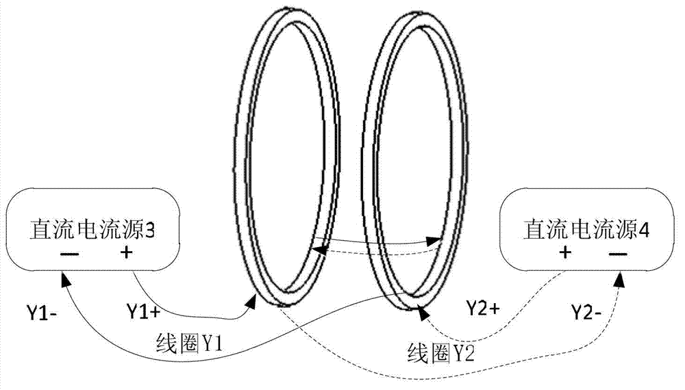
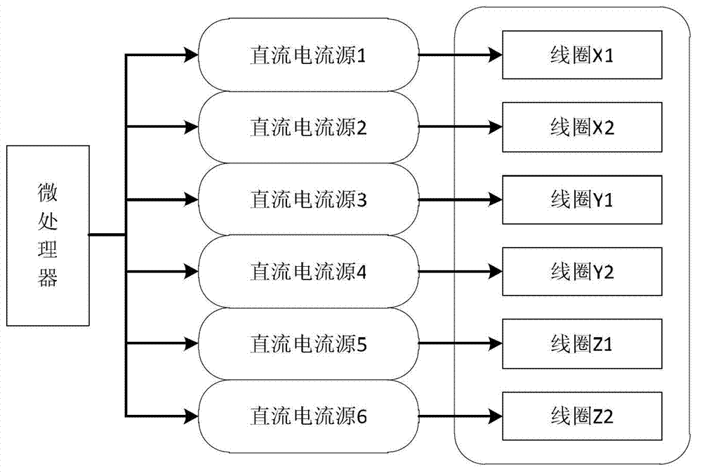
[0029] The magnetic field generating system of the present invention includes a coil, a power supply and a microcontroller.

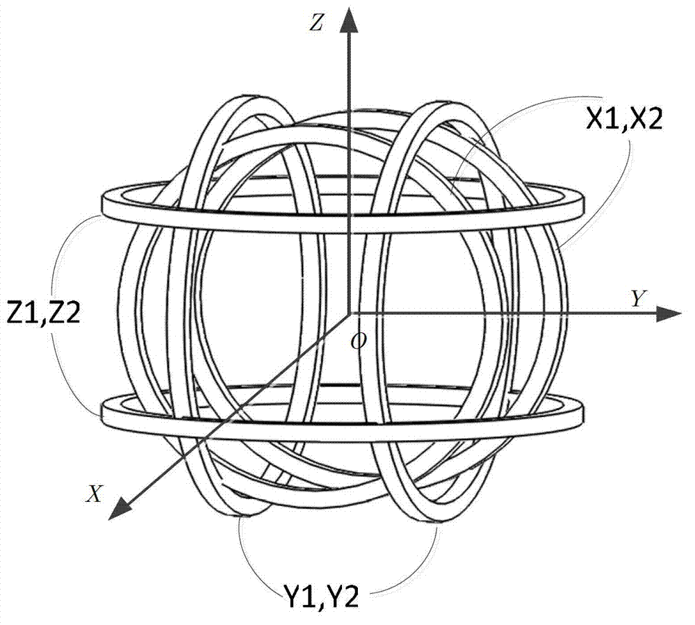
[0030]The usual Helmholtz coil is formed by using two coils with exactly the same radius and number of turns, which are arranged coaxially and whose spacing is equal to the radius, and connected in series. It has two terminals. Each group of Helmholtz coils in the present invention is made of bifilar winding, forming a group of two pairs of coils with the same geometric parameters and electrical parameters. Each pair of coils is a Helmholtz coil in the usual sense. The Mholtz coil has 4 terminals in total. The three sets of Helmholtz coils have 6 pairs of coils and 12 terminals.

[0031] Such as figure 1 As shown, the three sets of Helmholtz coils in the present invention are perpendicular to each other two by two, an...


PUM


Abstract

Disclosed are a rotating magnetic field generation system and a rotating magnetic field implementation method thereof. A coil comprises three sets of Helmholtz coils in a pairwise orthogonal manner. Each set of Helmholtz coils is formed by winding two pairs of coils in a combining manner, each pair of coils are both connected with controllable direct-current current sources. A micro-controller outputs current magnitude by controlling the direct-current current sources, and accordingly currents of the three sets of Helmholtz coils are controlled, and a spatial optionally-axial rotating magnetic field is produced.

Description

technical field [0001] The invention relates to a space rotating magnetic field generating system, in particular to a space rotating magnetic field generating system for driving a magnetic microrobot. Background technique [0002] With the development of society, rotating magnetic field has been used more and more. For example, in a microgravity environment, the external rotating magnetic field can be used to effectively control the thermal surface tension flow in the crystal growth of the floating zone method, thereby improving the quality of semiconductor crystal growth. The use of the rotating magnetic field can effectively remove the characteristics of inclusion particles in the liquid aluminum alloy melt, thereby providing an efficient method for purifying the metal melt. The structure of Bi-63%In hypoeutectic alloy and Bi-69%In hypereutectic alloy is improved and the cooling rate is accelerated by using a rotating magnetic field. Using a rotating magnetic field to ch...

Claims


Application Information

Patent Timeline
Patent Type & Authority Applications(China)
IPC IPC(8): H01F7/00G01R33/38A61B17/00
Inventor 徐建省
Owner INST OF ELECTRICAL ENG CHINESE ACAD OF SCI
Why Eureka
Try Eureka