Power unit board and method for driving switching tube of power unit board

A technology of a power unit and a driving method, applied in the direction of output power conversion devices, electrical components, etc., can solve the problems of inaccurate dead time value, unreliable PWM control, and simultaneous conduction of upper and lower switching tubes.

Active Publication Date: 2012-12-12
SHENZHEN INVT ELECTRIC
View PDF5 Cites 4 Cited by
  • Summary
  • Abstract
  • Description
  • Claims
  • Application Information

AI Technical Summary

Problems solved by technology

[0004] In the prior art, the main control board includes the dead time value in the PWM signal sent to the power unit board. Accu

Method used


Image

  • Power unit board and method for driving switching tube of power unit board
  • Power unit board and method for driving switching tube of power unit board
  • Power unit board and method for driving switching tube of power unit board

Examples


Embodiment Construction

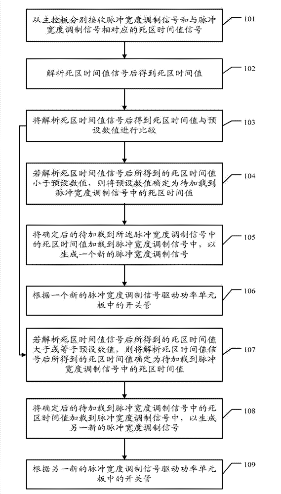
[0053] An embodiment of the present invention provides a method for driving a switch tube of a power unit board, which can ensure that the switch tube is driven with an accurate dead time value, and avoid simultaneous conduction of the upper and lower switch tubes. The embodiment of the present invention also provides a corresponding device. Each will be described in detail below.

[0054] refer to figure 1 , an embodiment of the switching tube driving method of the power unit board provided by the embodiment of the present invention, the power unit board is connected to the main control board through communication, and the switching tube driving method includes:

[0055] 101. Receive respectively a pulse width modulation signal and a dead zone time value signal corresponding to the pulse width modulation signal from the main control board.

[0056] The Pulse Width Modulation (PWM, Pulse Width Modulation) controller includes a main control board and a power unit board. The m...


PUM


Abstract

The invention discloses a method for driving a switching tube of a power unit board, which comprises the following steps of: respectively receiving a pulse width modulation signal from a master control board and a dead time value signal corresponding to the pulse width modulation signal; after the dead time value signal is analyzed, obtaining a dead time value; analyzing a dead time value signal to obtain a dead time value; comparing the dead time value obtained after the dead time value signal is analyzed with a preset numerical value; if the dead time value obtained by analyzing the dead time value signal is less than the preset numerical value, determining the preset numerical value as the dead time value to be loaded into the pulse width modulation signal; loading the determined dead time value to be loaded into the pulse width modulation signal into the pulse width modulation signal to generate a new pulse width modulation signal; and according to the new pulse width modulation signal, driving switching tubes in the power unit board. According to the method for driving the switching tube of the power unit board, which is disclosed by the invention, the upper switching tube and the lower switching tube are prevented from being simultaneously conducted.

Description

technical field [0001] The invention relates to the technical field of power electronics, in particular to a power unit board and a driving method for a switch tube thereof. Background technique [0002] The dead time is a protection period set for the pulse width modulation (PWM, Pulse Width Modulation) output, in order to prevent the upper and lower switches of the H bridge or half H bridge from being turned on at the same time due to the switching speed problem. [0003] Since power devices such as insulated gate bipolar transistors (IGBT, Insulated Gate Bipolar Transistor) have a certain junction capacitance, it will cause a delay in the turn-on and turn-off of the device. Generally, the influence has been reduced as much as possible when designing the circuit, such as increasing the driving voltage and current of the control electrode as much as possible, setting the junction capacitance release circuit, etc. In order to make the IGBT work reliably and avoid the simult...

Claims


Application Information

Patent Timeline
IPC IPC(8): H02M1/088
Inventor 李春辉黄申力
Owner SHENZHEN INVT ELECTRIC
Why Eureka
Try Eureka