Supercharge Your Innovation With Domain-Expert AI Agents!

Light module transmit enable control method, control device and light module

A control method and a technology of a control device, applied in the field of optical communication, can solve problems such as false light emission of lasers, and achieve the effects of solving false light emission and improving reliability and stability

Inactive Publication Date: 2012-12-12
HISENSE BROADBAND MULTIMEDIA TECH
View PDF5 Cites 5 Cited by
  • Summary
  • Abstract
  • Description
  • Claims
  • Application Information

AI Technical Summary

Problems solved by technology

[0004] The purpose of the present invention is to provide a method and a control device for controlling the emission of an optical module, so as to solve the problem that the laser emits light incorrectly due to improper control of the emission of the optical module in the prior art

Method used


Image

  • Light module transmit enable control method, control device and light module
  • Light module transmit enable control method, control device and light module

Examples


Embodiment Construction

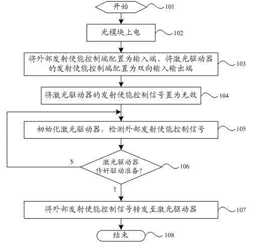
[0024] The technical solutions of the present invention will be further described in detail below in conjunction with the accompanying drawings and specific embodiments.
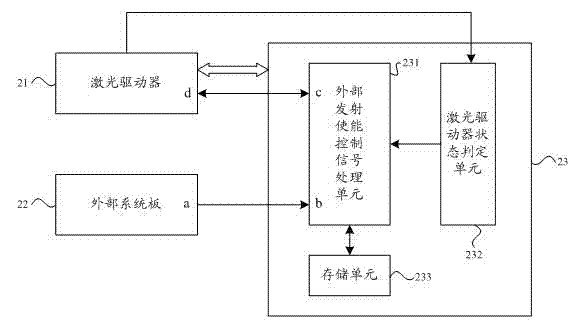
[0025] First, the design idea of ​​the present invention is briefly described: in the application of optical modules in the prior art, the realization scheme that the emission enable pin on the system board is directly connected to the enable end of the laser driver is adopted. If the external enable signal on the system board is an effective enable signal, such as a low-level signal, it will cause the enable end of the laser driver to be at a low level when the optical module is plugged in with power, causing the laser driver to fail before completing the configuration. Just drive the laser to emit light by mistake. In order to solve this problem, the present invention proposes to change the scheme that the emission enable pin on the system board is directly connected to the enable end of the laser driver, ...


PUM


Abstract

The invention discloses a light module transmit enable control method, a control device and a light module. The process of the control method comprises the following steps: after electrifying, a transmit enable signal of a laser driver in the light module is set as invalid; then an external transmit enable control signal is detected in real time, the detected external transmit enable control signal is used as the transmit enable control signal of the light module and transferred to the laser driver when the laser driver of the light module is prepared to drive. By controlling the transmit enable control signal, the external transmit enable control signal can be received only when the laser driver is prepared to drive, and controls the normal lighting of the laser according to the signal state, so that the situation of mistakenly lighting of the laser generated when the laser driver is not prepared to drive is avoided, and the reliability and the stability of the light module are improved.

Description

technical field [0001] The present invention relates to the technical field of optical communication, in particular to an optical module in an optical communication network, and more specifically to a method for controlling emission of an optical module, a control device and an optical module. Background technique [0002] In recent years, with the rapid expansion of the optical communication industry, the triple play of data communication, IP communication, and voice communication has accelerated, and the demand for optical modules has also increased day by day. [0003] Taking the SFP (Small Form-factor Pluggable, miniaturized hot-swappable optical module) optical module as an example, its laser driver has a launch enable terminal, which can determine whether to drive the laser to emit light under the control of the enable signal of the external system board. When the existing SFP optical modules are applied, they all adopt the implementation scheme that the launch enable ...

Claims


Application Information

Patent Timeline
Patent Type & Authority Applications(China)
IPC IPC(8): H04B10/155H01S3/102
Inventor 王三赵平
Owner HISENSE BROADBAND MULTIMEDIA TECH
Features
  • R&D
  • Intellectual Property
  • Life Sciences
  • Materials
  • Tech Scout
  • Unparalleled Data Quality
  • Higher Quality Content
  • 60% Fewer Hallucinations
Learn More