

Vertical wet-process winding device
A wet winding, vertical technology, applied in the field of winding forming devices, can solve the problems of low production efficiency, slow winding speed, unsuitable for large-scale industrial production, etc., and achieve the effect of good dynamic balance performance
- Summary
- Abstract
- Description
- Claims
- Application Information
AI Technical Summary
Problems solved by technology
Method used
Image

Examples
specific Embodiment approach 1
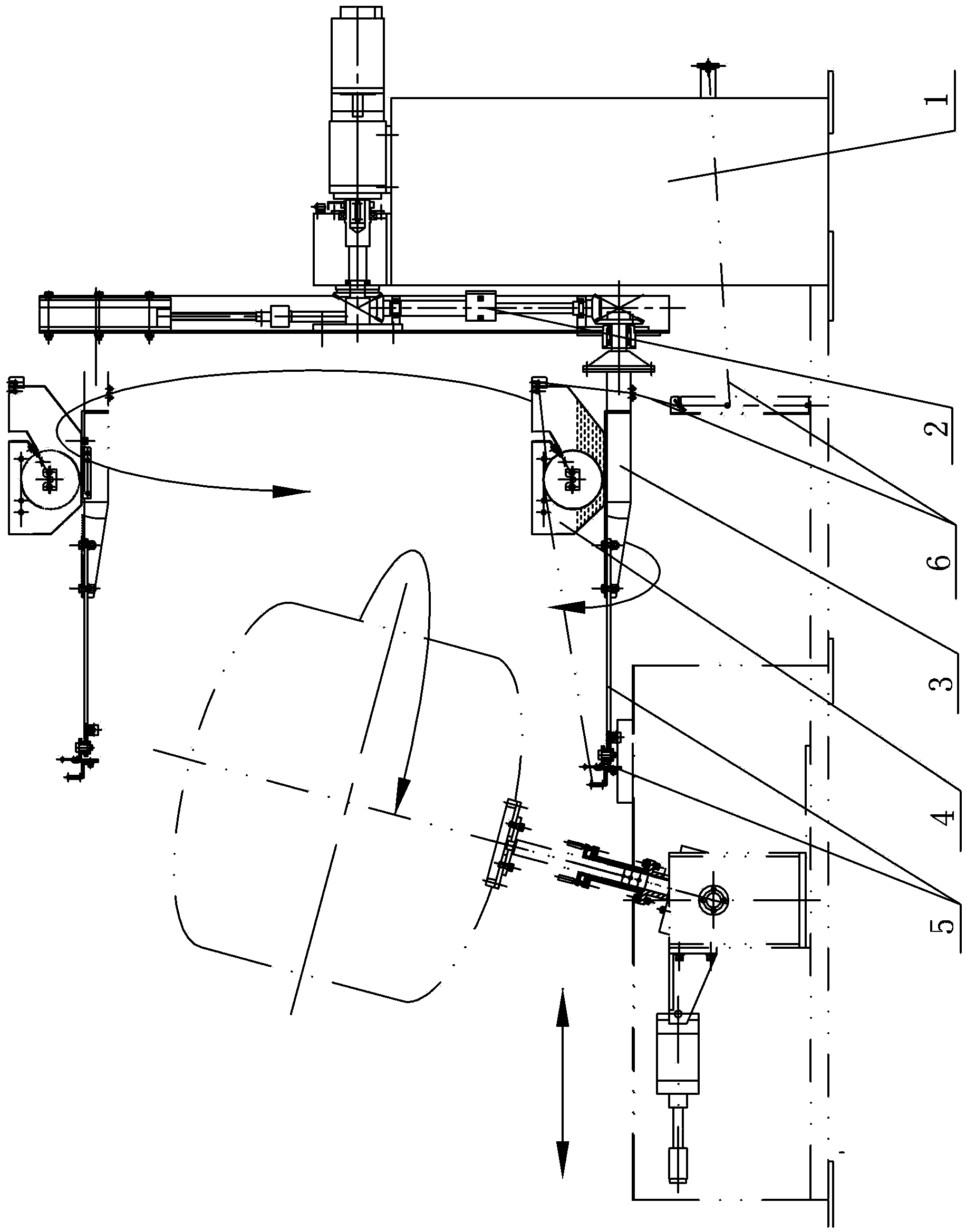
[0014] Specific implementation mode one: combine Figure 1-Figure 11 To illustrate this embodiment, the vertical wet winding device of this embodiment includes a main shaft drive system 1, an arm winding mechanism 2, a rotating bracket 3, a dipping mechanism 4 and a swinging yarn output mechanism 5;
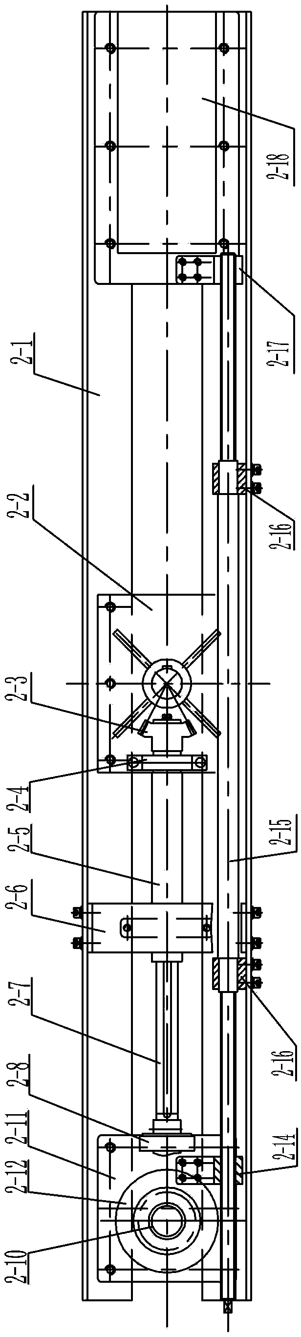
[0015] The arm winding mechanism 2 includes an arm beam 2-1, a flange 2-2, a shaft sleeve, a second bevel gear 2-3, a first sleeve shaft support 2-4, a sleeve shaft 2-5, a second sleeve Shaft support 2-6, sliding shaft 2-7, sliding shaft support 2-8, the third bevel gear 2-9, support shaft 2-10, turntable 2-11, sliding bearing seat 2-12, the fourth umbrella Gear 2-13, first screw nut 2-14, lead screw 2-15, second screw nut 2-17, balance weight body 2-18 and two lead screw supports 2-16, flange 2-2 Installed in the middle of the arm beam 2-1, the middle of the flange 2-2 is processed with a shaft hole 2-19, the main shaft transmission system 1 is connected with the shaft hole 2-1...
specific Embodiment approach 2
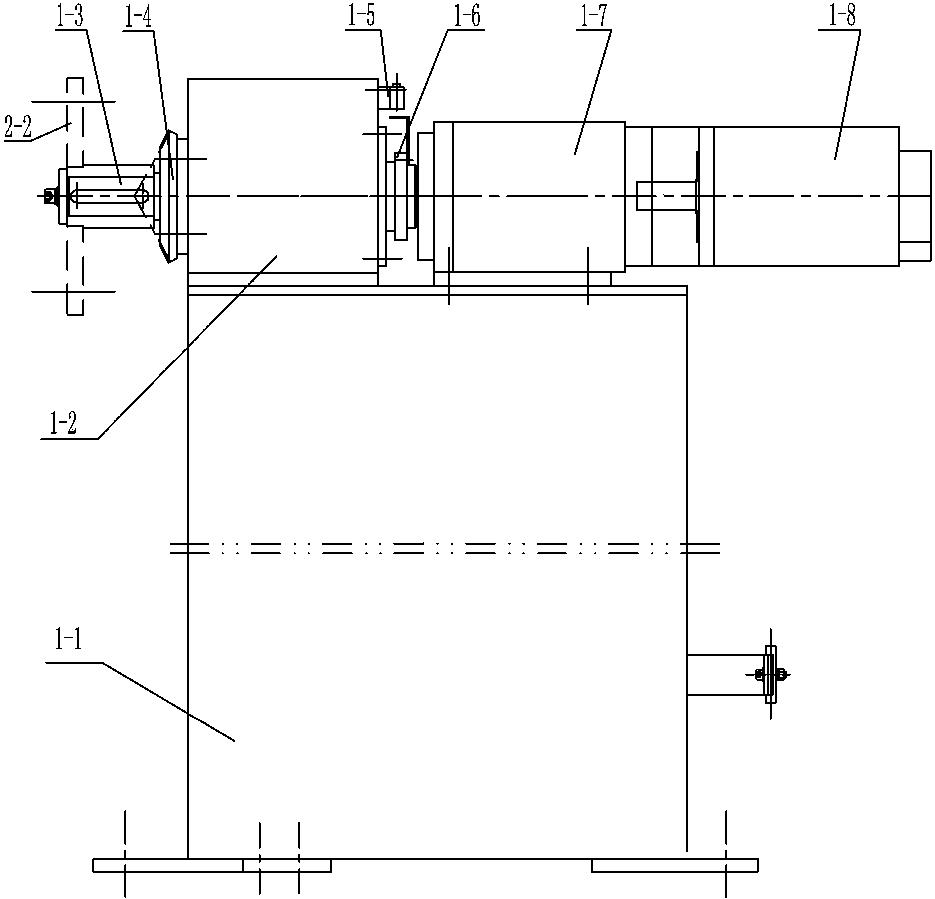
[0017] Specific implementation mode two: combination Figure 1-Figure 4Describe this embodiment, the spindle transmission system 1 described in this embodiment includes a lower box 1-1, an upper box 1-2, a main shaft 1-3, a first bevel gear 1-4, a proximity switch 1-5, and a sensor 1-6, reducer 1-7 and motor 1-8, the upper box 1-2 and the reducer 1-7 are installed on the upper surface of the lower box 1-1, one end of the main shaft 1-3 passes through the upper box 1-2 is connected to the output end of the reducer 1-7, the input end of the reducer 1-7 is connected to the output end of the motor 1-8, and the other end of the main shaft 1-3 is equipped with a first bevel gear 1-4, which is located at An inductor 1-6 is arranged on the main shaft 1-3 between the upper box body 1-2 and the reducer 1-7, and a proximity switch 1-6 is arranged on the upper box body 1-2 above the sensor 1-6. 5. The other end of the main shaft 1-3 is inserted into the shaft hole 2-19 provided in the mi...
specific Embodiment approach 3
[0018] Specific implementation mode three: combination figure 1 , Figure 5 and Figure 6 Describe this embodiment, the rotating bracket 3 described in this embodiment includes a bracket body 3-1, a yarn guide plate 3-2 and a fastener 3-3, and the lower surface of the bracket body 3-1 is provided with a The yarn guide plate 3-2, one end of the support body 3-1 is connected with the turntable 2-11, the other end of the support body 3-1 is detachably connected with the swinging yarn output mechanism 5 through the fastener 3-3, and the dipping tank The bottom surface of 4-1 is installed on the upper surface of the bracket body 3-1. In this embodiment, through the connection between the bracket body 3-1 and the dipping tank 4-1, the synchronous rotation of the dipping tank 4-1 and the winding arm mechanism 2 is effectively realized, while ensuring the smoothness of the yarn path, meeting the requirements of the glass fiber reinforced plastic sphere, The actual winding needs of ...
PUM
 Abstract
Description
Claims
Application Information