
Pneumatic bending press and bending method

A buckling machine and pneumatic technology, applied in the field of buckling, can solve the problems of large equipment volume, limited molding times, low production efficiency, etc., and achieve the effects of small equipment volume, environmental protection and simple structure

Inactive Publication Date: 2013-07-24
黄先全
View PDF1 Cites 2 Cited by
  • Summary
  • Abstract
  • Description
  • Claims
  • Application Information

AI Technical Summary

Problems solved by technology

At present, the koji machine used in most wineries is a hydraulic koji machine. This equipment has the following disadvantages: the "Baobao koji" produced by the liquor factory is fed by flat scraping, and the thickness of the raw materials in the mold cavity of the koji block is uniform, so the compression In the end, it will inevitably cause the periphery to be too tight and the middle to be too loose. The middle convex part of "Baobaoqu" often shows signs of cracking, and due to the limited number of moldings, it cannot achieve the surface pulping effect required by the koji making process; , resulting in a large amount of water loss in the early stage, affecting the fermentation quality of the koji block, thereby affecting the quality of liquor; After 7 to 9 times of pressing to form a curved block, as disclosed in the Chinese invention patent "Hydraulic Rotary Buckling Machine and its Buckling Method" on October 5, 2011, the publication number is: CN102206564A. Frame, rotary assembly, pressure assembly and curved material output table. The curved block is pressed continuously by seven pressure hammers. Although it will not have obvious effect on pulp extraction after seven pressures; due to the use of a rotary disc To realize the movement of the mold box, the equipment is large in size, complex in structure, and the number of bending blocks is pressed many times, resulting in low production efficiency. Because of the hydraulic transmission, the energy consumption is huge, and it is easy to cause hydraulic oil pollution and is not environmentally friendly.

Method used


Image

  • Pneumatic bending press and bending method
  • Pneumatic bending press and bending method
  • Pneumatic bending press and bending method

Examples


Embodiment Construction

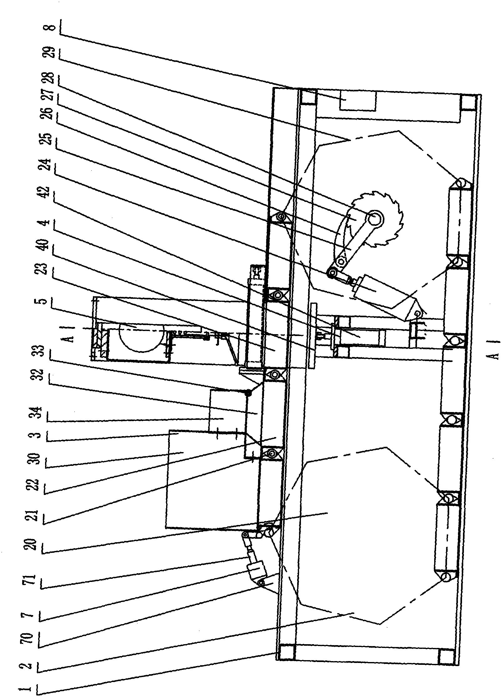
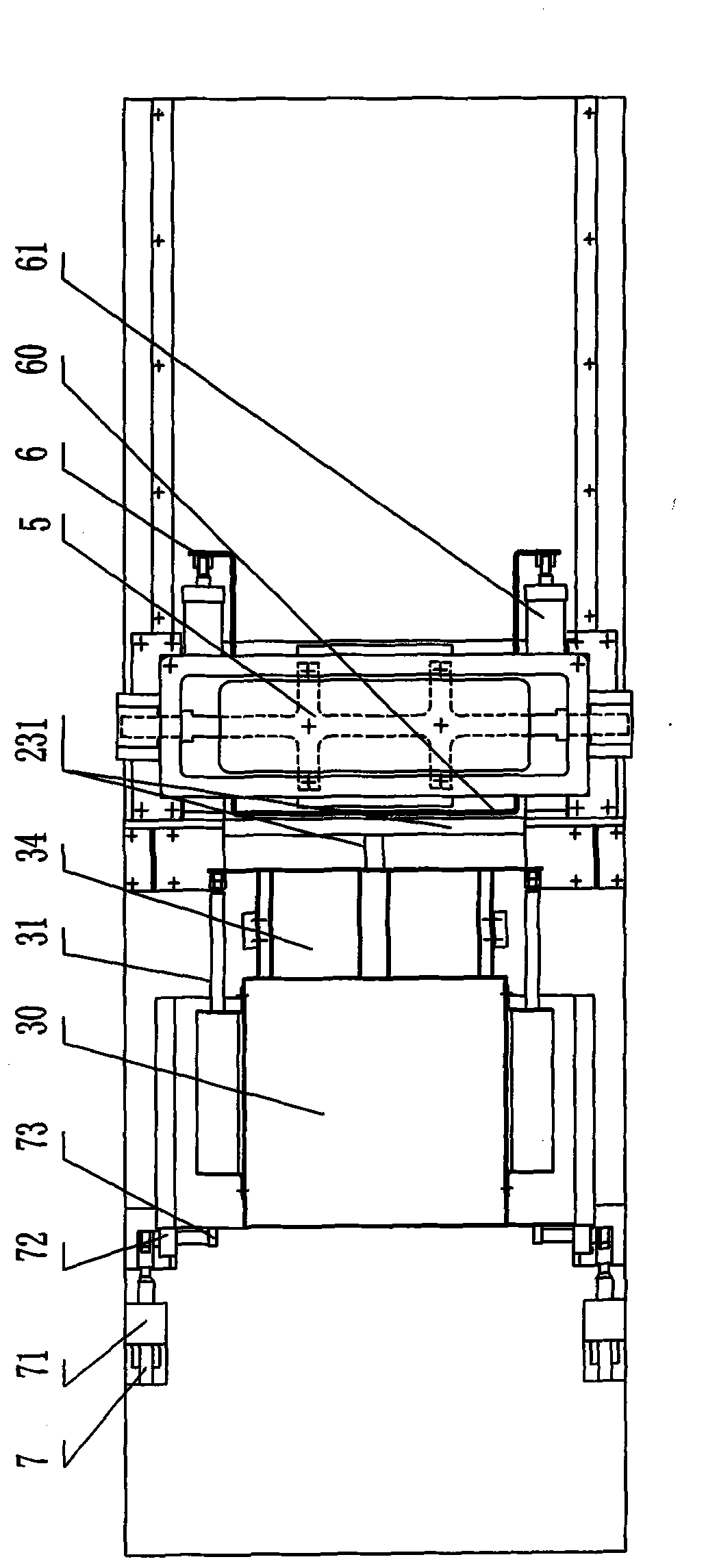
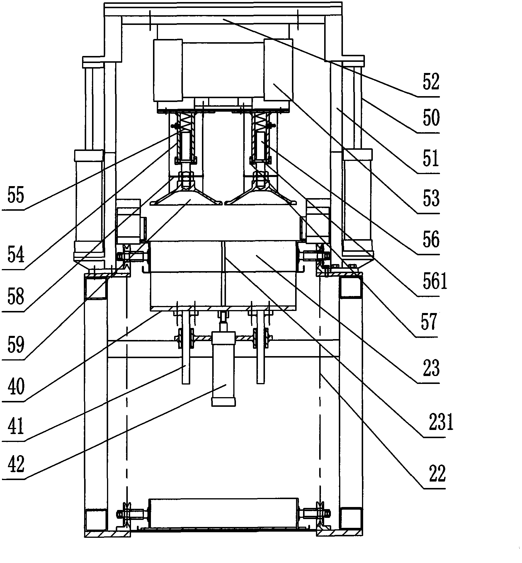
[0014] The pneumatic bending machine includes a frame 1, a chain transmission device 2 arranged on the frame 1, a profiling device 5, a feeding device 3, an ejecting device 4 and an output device 6, and the feeding device 3 includes a primary feeding box 30, a secondary Feeding box 34, feeding cover 32, feeding cylinder 31 connected to primary feeding box 30 and secondary feeding box 34 at both ends respectively, secondary feeding box 34 can freely enter and exit primary feeding box 30 under the action of feeding cylinder 31; profiling device 5 includes the mold slide rail 51, the mold cylinder 50 and the mold bracket 52 arranged on the frame 1, the mold bracket 52 is slidably matched with the mold slide rail 51, and the mold bracket 52 can be Move along the die slide rail 51; the die support 52 is provided with a vibrating motor 53, two die handle sleeves 54 and two die handles 59; The handle 56 is provided with a boss 561, and the boss 561 is slidingly matched with the inner...


PUM


Abstract

The invention relates to a pneumatic bending press and a bending method used for bending the koji blocks during a liquor production process. The invention provides the pneumatic bending press with the characteristics of energy preservation, environmental protection, high production efficiency, simple structure and good effect of slurry extraction of the koji blocks. The invention also provides the bending method by using the pneumatic bending press, which is characterized in that by twice additions and one time vibration compression, the inner part of the koji blocks has uniform tightness, due to high frequency multiple koji blocks surface compression, the surface of the koji blocks is moved, so that the slurry extraction and membrane sealing effects on the surface can be reached. The bending method comprises the following steps: 1, first addition is carried out in a mold box; 2, secondary addition is carried out in the mold box which completes the first addition; 3, the vibration andcompression are carried out on the koji blocks in the mold box by a compressing apparatus; and 4, outputting the koji blocks.

Description

technical field [0001] The invention relates to a koji machine used for pressing koji blocks in the liquor production process, especially a pneumatic koji machine, and also relates to a koji buckling method using the pneumatic koji machine. Background technique [0002] In the liquor brewing process, the quality of the koji pressing process and the koji block forming equipment directly affects the fermentation quality of the koji block, thereby affecting the quality of the liquor. High-quality liquor is inseparable from a good koji process, and the quality of the koji is largely determined by the koji forming equipment. With the large-scale production of liquor, it is an inevitable choice for the koji-making process in liquor production to replace artificial koji with a koji press. At present, the koji machine used in most wineries is a hydraulic koji machine. This equipment has the following disadvantages: the "Baobao koji" produced by the liquor factory is fed by flat scr...

Claims


Application Information

Patent Timeline
Patent Type & Authority Patents(China)
IPC IPC(8): C12G3/00
Inventor 黄先全
Owner 黄先全
Learn More