Auxiliary power supply for high power ups

An auxiliary power supply and high-power technology, applied in emergency power supply arrangements, electrical components, circuit devices, etc., can solve the problems of UPS failure, unstable output, easy damage, etc., to reduce voltage stress, improve reliability, and save energy. Effect

Active Publication Date: 2015-11-25
FOSHAN BAYKEE NEW ENERGY TECH INC
View PDF3 Cites 0 Cited by
  • Summary
  • Abstract
  • Description
  • Claims
  • Application Information

AI Technical Summary

Problems solved by technology

[0003] However, the auxiliary power supply for UPS power supply is generally realized by a simple single-ended flyback conversion circuit. When the input voltage of the auxiliary power supply composed of a single-ended flyback conversion circuit is relatively high, the power switch tube withstands a higher voltage, Current stress, easy to damage, and when the input voltage fluctuates greatly, it is easy to cause output instability and eventually cause UPS failure

Method used


Image

  • Auxiliary power supply for high power ups
  • Auxiliary power supply for high power ups
  • Auxiliary power supply for high power ups

Examples


Embodiment Construction

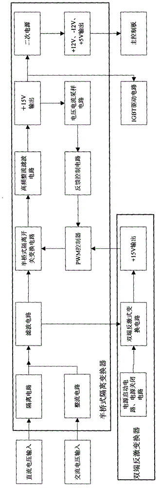
[0020] Such as figure 1 The auxiliary power supply of the high-power UPS shown, which includes: DC voltage input, AC voltage input, isolation circuit for preventing current backfeeding, rectification circuit, filter circuit, and a circuit for converting DC voltage into high-frequency PWM AC voltage Half-bridge isolation switch conversion circuit, high-frequency rectification and filtering circuit, voltage and current sampling circuit, feedback control circuit, PWM controller and a double-ended flyback converter for powering the PWM controller, the DC voltage input is first isolated in turn circuit and filter circuit for isolation and filtering, and then convert it into high-frequency PWM AC voltage through a half-bridge isolation switch conversion circuit, and then perform isolation coupling, rectification and filtering by a high-frequency rectification and filtering circuit to output DC voltage; the voltage and current sampling circuit will output the The voltage and current ...


PUM


Abstract

The invention discloses an auxiliary power supply of a high-power UPS (uninterrupted power supply). The auxiliary power supply comprises a direct-current voltage input, an alternating-current voltage input, an isolating circuit for preventing reverse-filling of current, a rectification circuit, a filter circuit, a half-bridge isolating switch conversion circuit, a high-frequency rectification filter circuit, a voltage and current sampling circuit, a feedback control circuit, a PWM (pulse width modulation) controller and a double-end fly-back converter. The direct-current voltage input is sequentially isolated and filtered via the isolating circuit and the filter circuit, is converted into high-frequency PWM alternating-current voltage by the half-bridge isolating switch conversion circuit, and is isolated, coupled, rectified and filtered by the high-frequency rectification filter circuit, and then direct-current voltage is output. The half-bridge isolating switch conversion circuit is controlled by the PWM controller to output stabilized direct-current voltage. An input end of the double-end fly-back converter is connected with an output end of the filter circuit so that the double-end fly-back converter can access to a power source, and the double-end fly-back converter supplies power to the PWM controller. The auxiliary power supply of the high-power UPS can supply reliable and stable direct-current voltage output to the UPS.

Description

technical field [0001] The invention relates to a UPS power supply, in particular to an auxiliary power supply for a high-power UPS. Background technique [0002] With the rapid development of power electronics technology, UPS has been developing towards high reliability. The logic control circuit in the UPS and the trigger drive circuit of the module all need DC auxiliary power supply, so the DC auxiliary power supply must be very reliable. [0003] However, the auxiliary power supply for UPS power supply is generally realized by a simple single-ended flyback conversion circuit. When the input voltage of the auxiliary power supply composed of a single-ended flyback conversion circuit is relatively high, the power switch tube withstands a higher voltage, Current stress is easy to damage, and when the input voltage fluctuates greatly, it is easy to cause unstable output and eventually cause UPS failure. Contents of the invention [0004] The technical problem to be solved ...

Claims


Application Information

Patent Timeline
Patent Type & Authority Patents(China)
IPC IPC(8): H02J9/06
Inventor 何木林潘世高黄敏
Owner FOSHAN BAYKEE NEW ENERGY TECH INC
Why Eureka
Try Eureka