Board housing case for vehicle-mounted electronic device

A technology for in-vehicle electronics and storage baskets, which is applied to electrical equipment shells/cabinets/drawers, electrical components, electrical equipment structural parts, etc. Divergence and other issues, to achieve the effect of averaging, heat dissipation, and stable heat dissipation

Inactive Publication Date: 2012-12-19
MITSUBISHI ELECTRIC CORP
View PDF5 Cites 17 Cited by
  • Summary
  • Abstract
  • Description
  • Claims
  • Application Information

AI Technical Summary

Problems solved by technology

Therefore, there is a problem that sufficient heat dissipation cannot be performed when the cover (base) side is in a high-temperature environment and the case (cover) is in a low-temperature environment.
[0012] In addition, there is a disadvantage that the main heat-generating parts are generally larger than other small heat-generating parts and the thickness dimension on the cover (base) side is increased, and there is a problem that when there is a deviation in the height dimension of the heat-generating parts, the heat-transmitting member Thickness dimensions can vary, resulting in large changes in heat transfer characteristics or stress on soldered connection terminals
Therefore, the thickness dimension on the base side does not increase, even if there is a deviation in the height dimension of the heat-generating parts, the heat transfer characteristics will not change, and the stress on the soldered connection terminal will not be generated. Heat radiation on the (cover) side, so there is a problem that the temperature rise of the heat-generating parts cannot be sufficiently suppressed when the ambient temperature on the base side is higher than the ambient temperature on the case (cover) side
[0015] In addition, in the above-mentioned Patent Document 3 "Electronic Substrate Mounting Structure", although heat transfer and heat dissipation to the base are carried out, heat dissipation due to heat radiation to the cover is not considered. Therefore, there is The following problem: When the ambient temperature on the base side is higher than the ambient temperature on the cover side, the temperature rise of the heat-generating parts cannot be sufficiently suppressed
[0016] In addition, in the above-mentioned Patent Document 4 "Electronic Substrate Device", the heat generated by the heat-generating parts is dissipated to both the base side and the cover side, and when there is a deviation in the height dimension of the heat-generating parts, the heat transfer The thickness dimension of the parts will change, so there are disadvantages in that the heat transfer characteristics are greatly changed or the stress on the soldered connection terminals is generated.

Method used


Image

  • Board housing case for vehicle-mounted electronic device
  • Board housing case for vehicle-mounted electronic device
  • Board housing case for vehicle-mounted electronic device

Examples


Embodiment approach 1

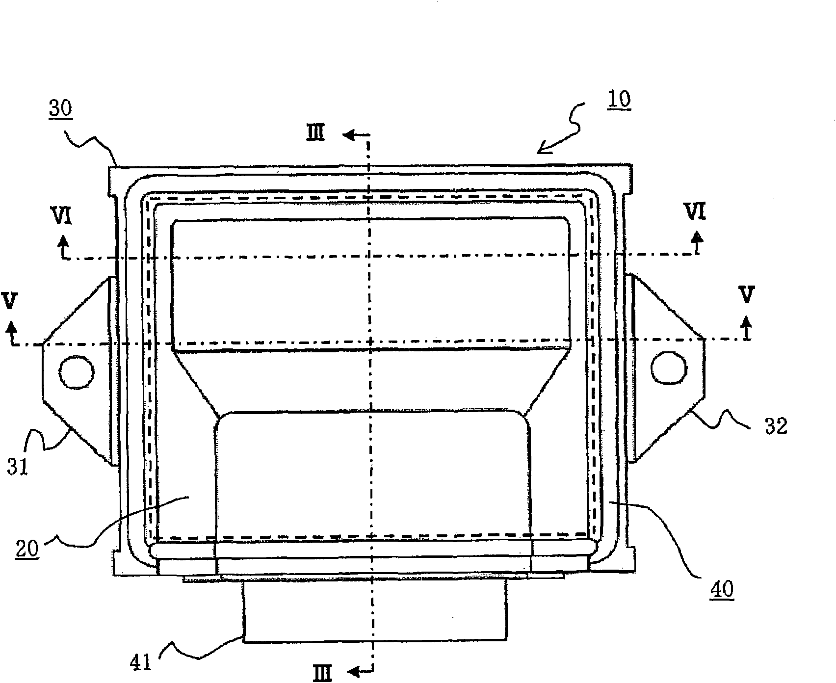
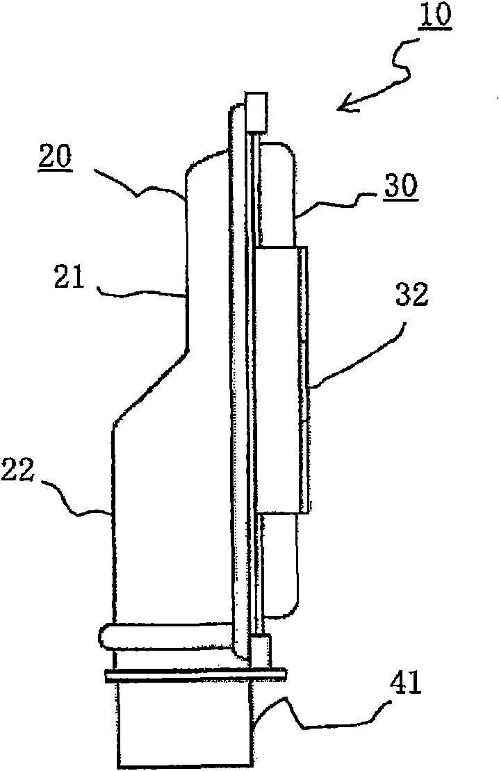
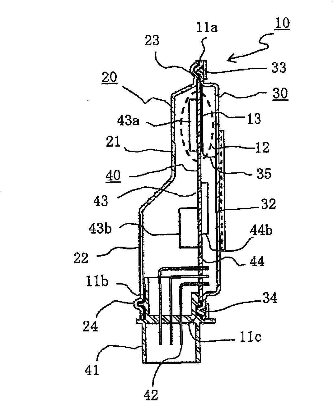
[0096] Hereinafter, the plan view of the substrate housing case of the vehicle-mounted electronic device according to Embodiment 1 of the present invention will be described in order. figure 1 , figure 1 The right side view of the board storage case of the in-vehicle electronic device is figure 2 , figure 1 The sectional view taken along line III-III of the substrate storage case of the vehicle-mounted electronic device is image 3 , figure 1 The bottom view of the substrate storage case of the on-board electronic device is Figure 4 , figure 1 The cross-sectional view of the board storage case of the vehicle-mounted electronic device taken along line V-V is Figure 5 , figure 1 The sectional view of the VI-VI line of the board storage case of the vehicle-mounted electronic device is Figure 6 and figure 1 The external view of a single part of the cover in the substrate storage case of the vehicle-mounted electronic device is Figure 7 Although detailed description w...

Embodiment approach 2

[0154] Hereinafter, a cross-sectional view of the heat transfer mechanism 12A of the substrate housing case of the vehicle-mounted electronic device according to Embodiment 2 of the present invention is Figure 10 and Figure 11 and top view i.e. Figure 12 and Figure 13 Be explained.

[0155] Figure 11 yes Figure 10 The cross-sectional view taken along line XI-XI in , in each figure, the same symbols indicate the same or corresponding parts.

[0156] In addition, this Embodiment 2 shows the detail of the heat transfer mechanism 12 of Embodiment 1, and other code|symbols refer to the original code|symbol or the code|symbol A is added and identified.

[0157] exist Figure 10 , Figure 11 Among them, on the heat transfer base portion 35A having a plurality of isolation protrusions 36A, 36A, an electronic substrate 40A is arranged via a slit G1 limited by the height dimension of the isolation protrusion 36A, and on the opposite side of the electronic substrate 40A A h...

Embodiment approach 3

[0180] according to Figure 14 Embodiment 3 of the present invention will be described. Figure 14It is a sectional view showing the heat transfer mechanism in the substrate housing case of the in-vehicle electronic device according to Embodiment 3 of the present invention. This Embodiment 3 shows the details of the heat transfer mechanism 12 in the above-mentioned Embodiment 1, and other symbols are identified by referring to the original symbols or by adding the symbol B. FIG.

[0181] exist Figure 14 Among them, on the first substrate surface 43 of the circuit board 40B, a heating part 43Ba is mounted, and the heating part 43Ba is composed of a heating element 43Bb mounted on a die pad 46B as a heat transfer member and a plurality of surface connection electrodes 45, 45. The connection electrodes 45 and 45 are connected by soldering to the wiring pattern 48c provided on the first substrate surface 43 of the circuit board 40B.

[0182] The circuit board 40B is provided w...


PUM


Abstract

A circuit board is hermetically-sealed and housed in a steel case that is composed of a metal base (30) and a metal cover (20), the cover disposed opposite to a first board surface (43) has a tall flat portion disposed opposite to a connector housing (41) and a short flat portion (22) disposed opposite to a heating component (43a), and the heat generated from the heating component is directly transferred to a heat transfer base portion (35) of the base via a heat transfer mechanism (12) and a heat transfer filling material (13). Surface finishing in which the coefficients of heat radiation are mutually 0.7 to 1.0 is applied to the surface of the heating component (43a) and the opposite inner surface of the cover (20), and radiation and heat transfer are efficiently performed to the short flat portion (21) of the cover.

Description

technical field [0001] The present invention relates to an improvement of a substrate storage case related to an electronic circuit substrate for a vehicle-mounted electronic control device, in particular, an improved structure of a substrate storage case of a vehicle electronic device improved in the following manner: The heat generated by the heat-generating components mounted on the circuit board is efficiently diffused to the metal housing by means of heat transfer and radiation, so that it can be transmitted from the pair of bases and covers that constitute the metal housing to the outside of the housing. Heat dissipation. Background technique [0002] Airtightly store the circuit board with the heat-generating parts in the metal case composed of the base and the cover, so that the heat generated by the heat-generating parts can be transferred to the base or the cover through the heat-transfer parts, or as radiant heat. Indirect radiation to the inner surface of the ba...

Claims


Application Information

Patent Timeline
Patent Type & Authority Applications(China)
IPC IPC(8): H05K7/20H05K5/06
CPCH05K5/061H05K5/0052H05K7/20445H05K7/20481H05K7/20854
Inventor 桥本光司安积功松田裕介西马由岳
Owner MITSUBISHI ELECTRIC CORP
Why Eureka
Try Eureka