Friction-driving trolley type conveying device

A technology of friction drive and handling device, which is applied in the direction of transportation and packaging, conveyors, mechanical conveyors, etc., which can solve the problem of requiring a very large floor area and achieve the effect of light weight and cost

Active Publication Date: 2012-12-26
DAIFUKU CO LTD
View PDF7 Cites 9 Cited by
  • Summary
  • Abstract
  • Description
  • Claims
  • Application Information

AI Technical Summary

Problems solved by technology

In addition, when the friction-driven rod of the closed structure that can be bent freely in the horizontal direction is frictionally driven along the horizontal curved path, the transfer table protrudes from the front and rear ends of the rod unit mounted on the transfer trolley in the front and re

Method used


Image

  • Friction-driving trolley type conveying device
  • Friction-driving trolley type conveying device
  • Friction-driving trolley type conveying device

Examples


Embodiment Construction

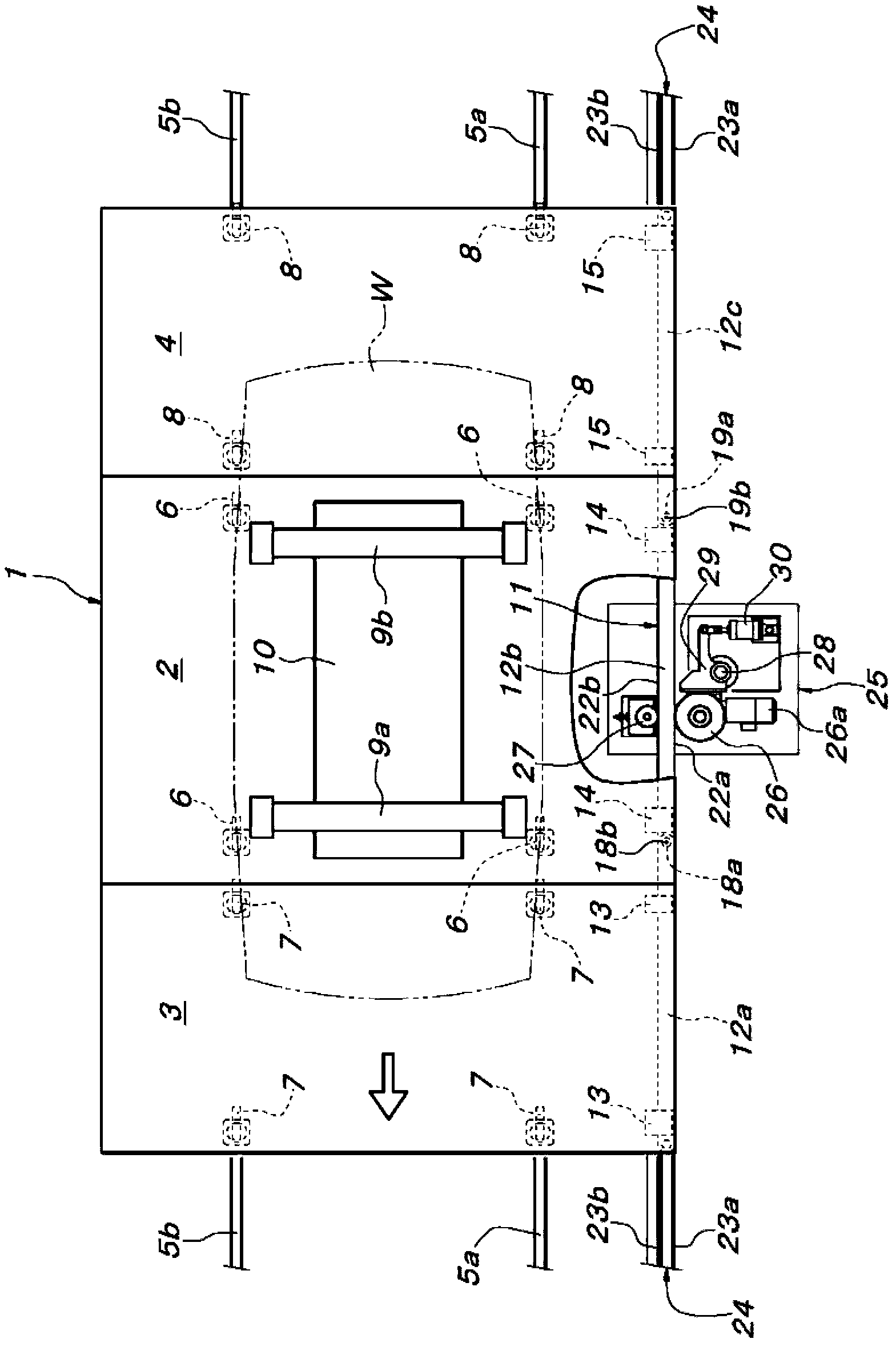
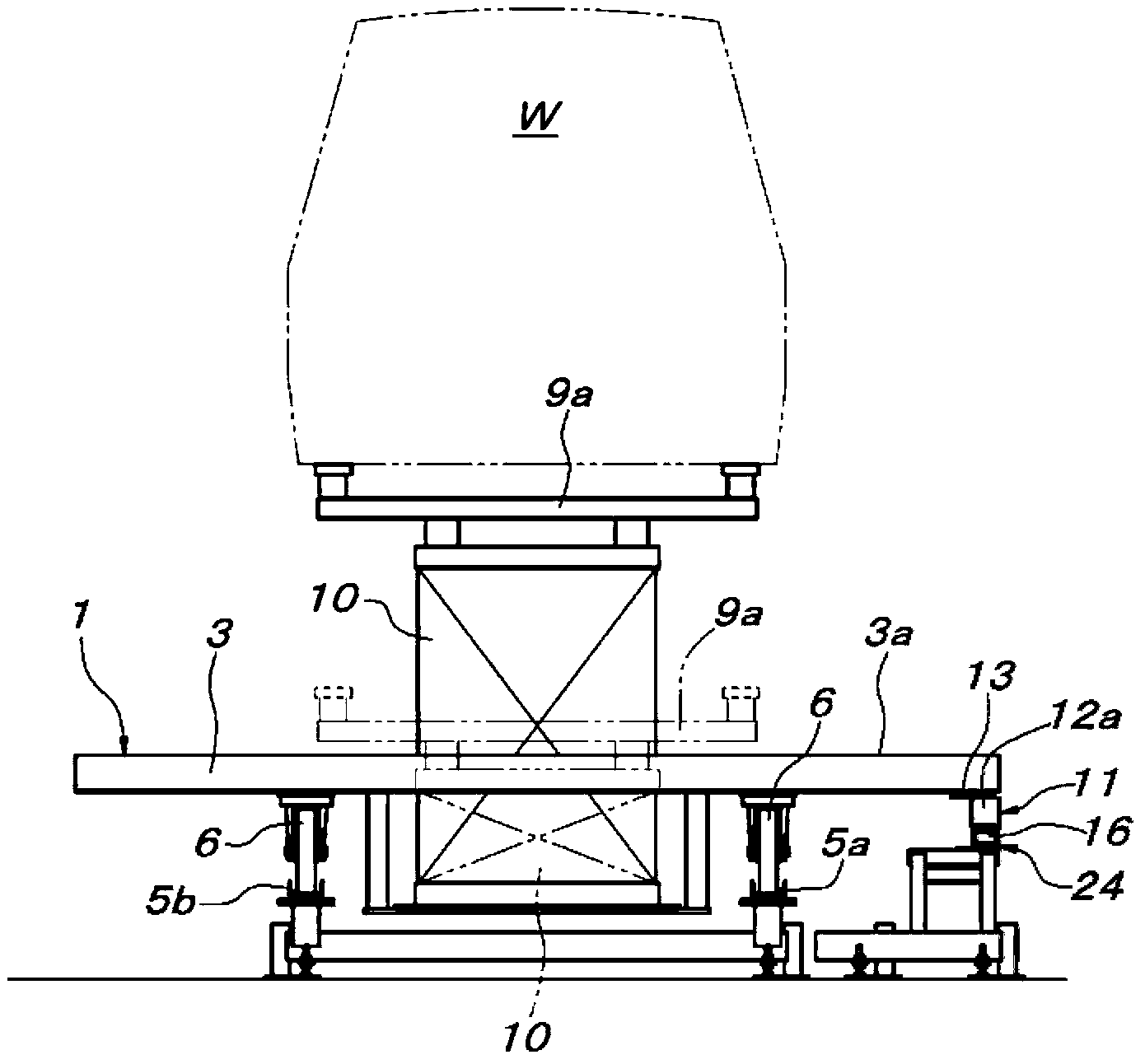
[0093] Moving trolleys such as Figure 1 ~ Figure 4B As shown, it is composed of a central trolley unit 2 located in the center of the traveling direction, a front trolley unit 3 and a rear trolley unit 4 adjacent to the front and rear. Each trolley unit 2-4 is equipped with a left and right pair of front and rear free wheels 6-8, which can rotate on a left and right pair of rails 5a, 5b laid along the travel path. The central carriage unit 2 is provided with a pair of front and rear object support platforms 9a, 9b, and an elevating drive device 10 that drives the two object support platforms 9a, 9b in parallel.

[0094] The structure of this lifting drive device 10 is the structure of the prior art, so the illustration and description of the structure are omitted. A lifting drive device consisting of a pressure cylinder unit or a motor-driven screw jack, a chain that can be pushed up and down freely, etc. The elevating drive device 10 is installed so as to protrude from the...


PUM


Abstract

The invention discloses a friction-driving trolley type conveying device, which can be used for the operator of the vehicle assembly line to take the conveying trolley for the vehicle assembly operation. The conveying trolley 1 is constituted by a plurality of serially connected trolley single bodies 2-4 along the walking direction. One of a left side and a right side of the conveying trolley 1 having the trolley single bodies 2-4 under the forwarding state is connected with the periphery of the vertical joint axial central 18b, 19b of the straight line position parallel to the walking direction in a freely bendable manner. The friction driving rod 11 is disposed on each of the trolley bodies single bodies 2-4, and is constituted by a plurality of rod single bodies 12a-12c disposed the straight line position, besides, the rod single bodies 12a-12c can be freely bent around the joint axial center 18b,19b in the horizontal direction.

Description

technical field [0001] The present invention relates to a friction-driven trolley-type conveying device composed of a friction-driven device. The friction-driven device includes a conveying trolley with a friction-driven rod arranged along the traveling direction, and a conveying trolley arranged on the traveling path of the conveying trolley. Friction drive wheel crimping above lever. Background technique [0002] The friction-driven trolley-type conveying device of the above-mentioned structure, such as the conveying device described in Patent Document 1, the friction-driven rod is composed of a plurality of rod monomers arranged in series along the traveling direction to be horizontal around the vertical joint axis circumferential direction. It is connected in a free bending manner, and one of the friction drive rods (specifically, the central rod single body) is used to support the object support platform, so that the length of the friction drive rod The pulley at the p...

Claims


Application Information

Patent Timeline
IPC IPC(8): B65G35/06
Inventor 大江正浩
Owner DAIFUKU CO LTD
Why Eureka
Try Eureka