Steam drive type compression device

A compression device, a steam-driven technology, applied to the parts of the pumping device for elastic fluid, the pump parts of the rotary piston type/oscillating piston type, machines/engines, etc. question

Active Publication Date: 2012-12-26
코벨코컴프레서가부시키가이샤 +1
View PDF12 Cites 3 Cited by
  • Summary
  • Abstract
  • Description
  • Claims
  • Application Information

AI Technical Summary

Problems solved by technology

Therefore, the conventional steam-driven compression device cannot prevent the re

Method used


Image

  • Steam drive type compression device
  • Steam drive type compression device
  • Steam drive type compression device

Examples


Embodiment Construction

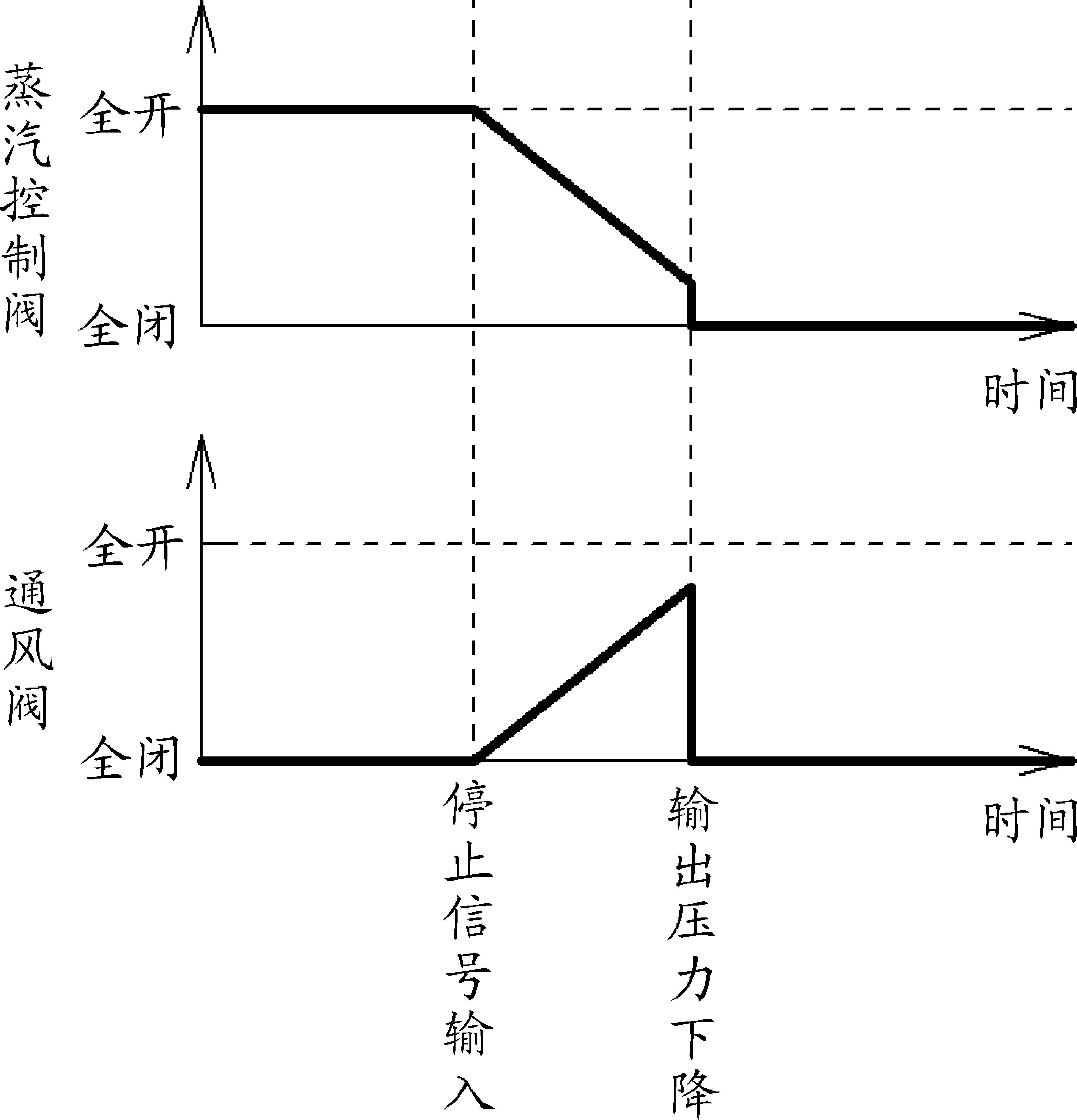
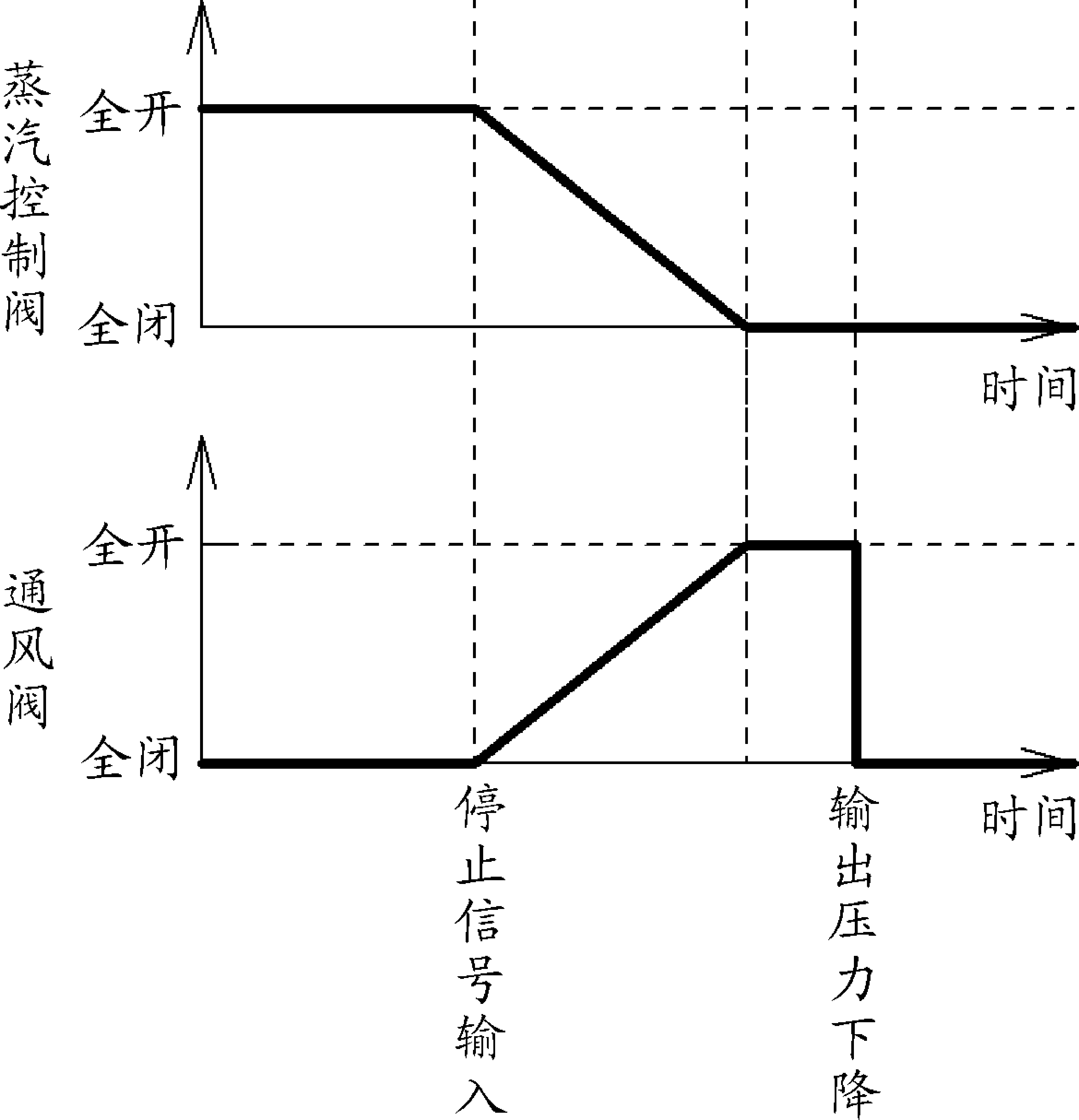
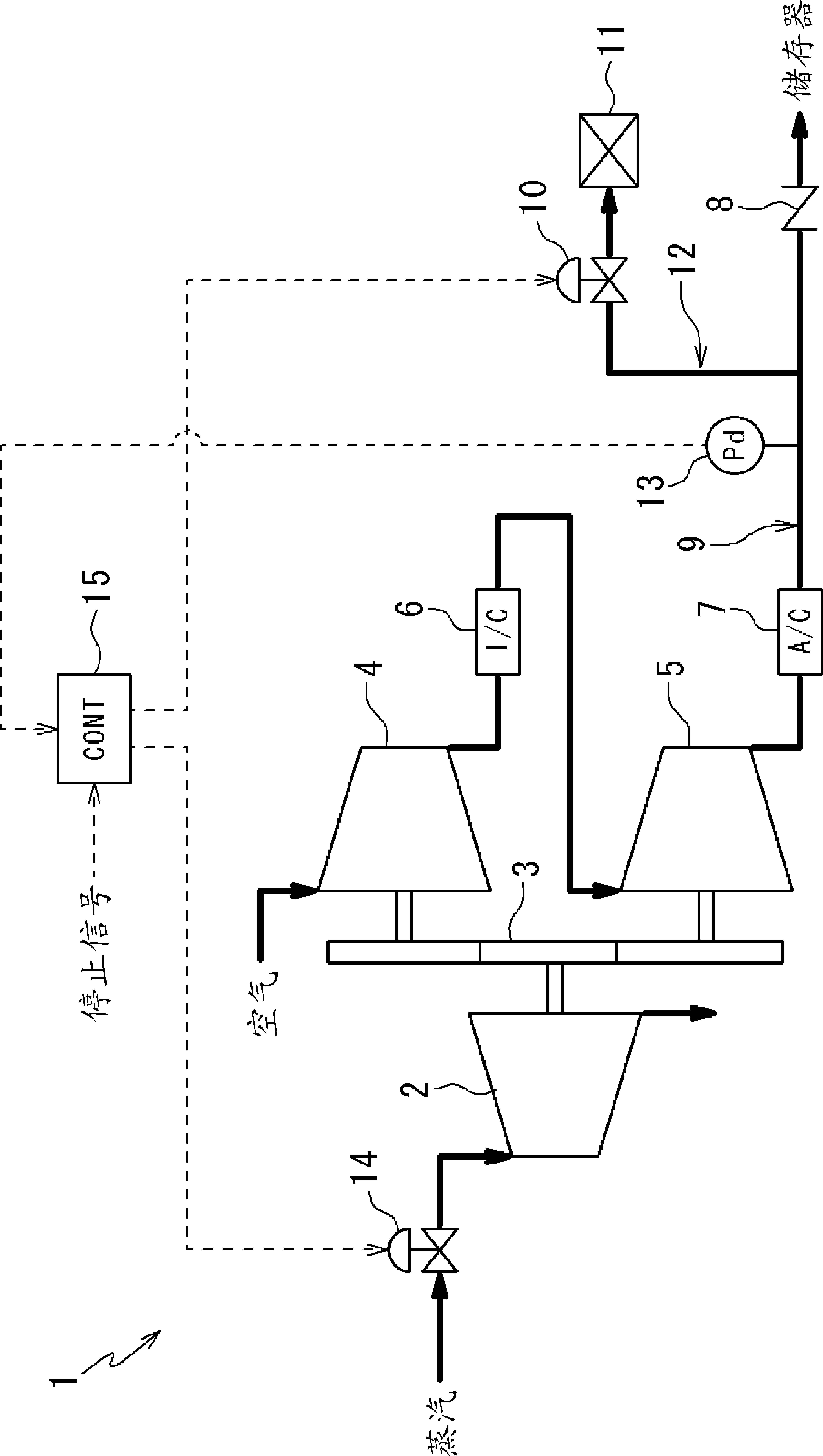
[0033] Embodiments of the present invention will be described below with reference to the drawings. first, figure 1 A steam-driven compression device 1 according to a first embodiment of the present invention is shown in . The steam-driven compressor 1 is a compressed air manufacturing device that uses air as a target gas to be compressed.

[0034] The steam-driven compression device 1 has a steam expander 2, a first-stage compressor 4, and a second-stage compressor 5. The steam expander 2 converts the expansion force of steam into a rotational force. The first-stage compressor 4 and the second-stage compressor 5 The compressor 5 is driven by the steam expander 2 through the gear 3 to compress the air. The steam expander 2 is a screw expander in which a pair of male and female screw rotors are housed in a casing, and the screw rotors are rotated by expanding steam in a closed space in the slots of the screw rotors. The first-stage compressor 4 and the second-stage compresso...


PUM


Abstract

The invention provides a steam drive type compression device (1), which does not reverse on stop. The steam drive type compression device comprises a steam expansion machine (2) for converting expansion force of steam into rotation force; compressors (4, 5) driven by the steam expansion machine (2) to compress an object gas; an output path (9) for outputting the compressed object gas from the compressor (5), and provided with a check valve (8); and a ventilation path (12) branched from the output path (9) on the upstream side of the check valve (8), and opening outwards through a ventilation valve (10). The steam drive type compression device is characterized by comprising a steam control valve (14) for controlling the flow amount of the steam of the steam expansion machine (2); an output pressure detector (13) for detecting the pressure of the output path (9) on the upstream side of the check valve (8); and a stop control device (15) for opening the ventilation valve (10) until the detection value of the output pressure detector (13) is below the given setting pressure when the compressors (4, 5) stop driving.

Description

technical field [0001] This invention relates to steam driven compression devices. Background technique [0002] In a device that uses steam generated by a boiler, generally speaking, the medium-pressure (such as 1.2-1.6MPa) steam generated by the boiler is decompressed by a pressure reducing valve, and then the low-pressure (such as 0.8-0.9MPa) steam is supplied to the required device of. If the steam is decompressed by the pressure reducing valve, energy corresponding to the pressure difference of the steam is wasted, and therefore, it is desirable to recover the energy. [0003] Patent Document 1 describes a steam-driven compression device that uses steam to drive a screw steam expander (steam motor or steam terminal), converts the pressure energy of the steam into rotational force and recovers it, and utilizes the steam expander The rotational force drives the screw compressor (head, air end) to compress the air. In the steam-driven compression device of Patent Docume...

Claims


Application Information

Patent Timeline
IPC IPC(8): F04C23/02F04C28/24
CPCF01C1/16F01C13/04F04C23/02F04C28/24F04C29/124F04C2210/22F04C2240/30Y10S415/00Y10S417/00
Inventor 山本祐介中西海
Owner 코벨코컴프레서가부시키가이샤
Why Eureka
Try Eureka