Die clamping bolt and tube pile forming die comprising die clamping bolt

A molding die and bolt technology, applied in the direction of screws, molds, connecting components, etc., can solve the problems of high manufacturing cost, slow speed, failure of mold closing or mold opening, etc., and achieve the effects of improving service life, reliable matching, and convenient replacement

Active Publication Date: 2015-05-27
浙江兆弟技术有限公司
View PDF7 Cites 0 Cited by
  • Summary
  • Abstract
  • Description
  • Claims
  • Application Information

AI Technical Summary

Problems solved by technology

Its disadvantages: First, it is necessary to change the structure of the existing pipe pile forming mold, and install a spring sleeve on the clamping edge of the pipe pile forming mold. Not only the manufacturing cost is high, but also the cement slurry can easily enter the spring sleeve, which directly affects the spring. Normal work; Second, because the lower part of the bolt and the edge of the lower die are screwed with threads, not only is the mold clamping screwing difficult and slow, but also the cement slurry enters the thread, which makes it impossible to screw the mold
[0005] The disadvantages of above-mentioned CN102431088A and CN202062504U: because the spring is exposed on the pipe pile forming, when the concrete is distributed on the pipe pile forming mold, the concrete slurry will inevitably fall on it, causing the spring to fail to work normally, and the mold closing or opening die failure

Method used


Image

  • Die clamping bolt and tube pile forming die comprising die clamping bolt
  • Die clamping bolt and tube pile forming die comprising die clamping bolt
  • Die clamping bolt and tube pile forming die comprising die clamping bolt

Examples


Embodiment 1

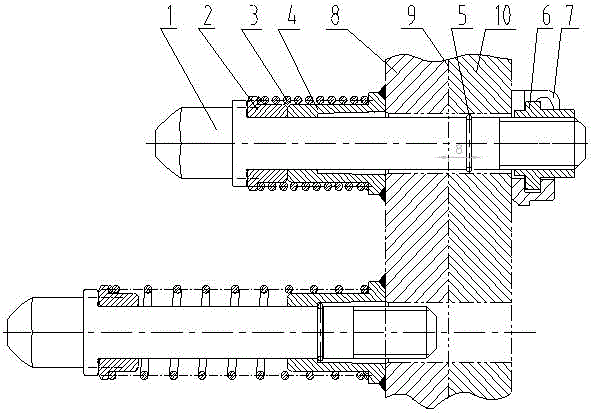
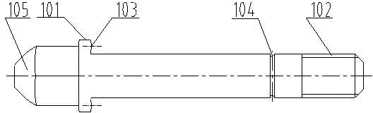
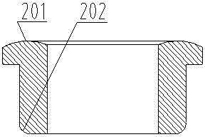
[0019] Example 1: refer to the attached Figure 1-8 . A clamping bolt, the upper part of the clamping bolt rod 1 is provided with a circle of bosses 101, the lower part of the clamping bolt rod 1 is covered with a thread 102, the flange-type movable spring seat 2 and the flange inner ring boss-type fixed spring seat 4 are sleeved. A spring 3 is sleeved on the clamping bolt rod 1 and the flange-type movable spring seat 2 and the sleeve wall of the flange inner ring boss-type fixed spring seat 4, and one end of the spring 3 is connected to the flange-type movable spring seat 2 flange ring wall. In contact, the other end is in contact with the flange ring wall of the flange inner ring boss-type fixed spring seat 4, the lower part of the clamping bolt rod 1 has a ring slot 104 and is located on the upper part of the screw 102, and the shaft steel wire retaining ring 5 is stuck in On the card groove, the shaft wire retaining ring 5 protrudes on the surface of the clamping bolt rod...

Embodiment 2

[0020] Embodiment 2: On the basis of Embodiment 1, a matching structure of a clamping bolt and a pipe pile forming die, including a pipe pile forming die (8, 10), a flange inner ring boss in the clamping bolt to fix the spring seat The chamfered surface 401 of the flange ring in 4 is welded with the upper die 8 in the pipe pile forming die, and the spring 3 is sleeved on the flange type movable spring seat 2 and the flange inner ring boss type fixed spring seat 4 sleeve wall , and then the clamping bolt rod 1 passes through the flange-type movable spring seat 2, the flange inner ring boss-type fixed spring seat 4 and the die edge of the pipe pile forming mold (8, 10), and the upper boss 101 of the clamping bolt rod 1 is connected to The flange ring in the flanged movable spring seat 2 is in contact, and the shaft steel wire retaining ring 5 is clamped on the groove of the lower part of the clamping bolt rod 1 and is in the fixed sleeve of the flange inner ring convex table fixe...


PUM


Abstract

The invention relates to a die clamping bolt and a tube pile forming die comprising the die die clamping bolt. A circle of boss is arranged at the upper part of a die clamping bolt rod; a screw thread is sleeved at the lower part of the die clamping bolt rod; a flange-type movable spring seat and a flange inner ring boss-type fixed spring seat are sleeved on the die clamping bolt rod; springs are sleeved on the sleeve walls of the flange-type movable spring seat and the flange inner ring boss-type fixed spring seat; one end of each spring is contacted with the wall of the flange ring of the flange-type movable spring seat; the other end of each spring is contacted with the wall of the flange ring of the flange inner ring boss-type fixed spring seat; a circle of clamping slot is arranged at the lower part of the die clamping bolt rod and at the upper part of the screw thread; an axle steel cable baffle ring is clamping in the clamping slot and is in limited match with the inner ring boss in the flange inner ring boss-type fixed spring seat; a boss die clamping nut is spirally matched with the screw thread at the lower part of the die clamping bolt rod; and a nut clamping seat and the boss die clamping nut are in clamped match. The die clamping bolt has the advantages that: 1, matched joint of the die clamping bolt and the tube pile forming die can be achieved, and the purposes of rapid die sinking and die assembly are achieved; and 2, a die clamping spring is convenient to replace.

Description

technical field [0001] The invention relates to a mold clamping bolt which can not only facilitate the replacement of mold clamping springs, but also has convenient mold clamping or mold opening, and a pipe pile forming mold composed of the mold clamping bolts, belonging to a pipe pile clamping bolt and a pipe pile forming mold. manufacturing field. Background technique [0002] CN101787699A, titled "a pipe die bolt connection structure", comprising a mounting hole arranged in the upper die, a screw hole arranged in the lower die, and a bolt inserted in the mounting hole and connected with the screw hole, it is characterized in that the An outer spring card is installed on the bolt, an inner spring card is installed in the installation hole, a spring is sleeved on the bolt between the outer spring card and the inner spring card, and a bolt head is installed at the installation hole. Its shortcomings: First, the structure of the existing pipe pile forming mold needs to be ch...

Claims


Application Information

Patent Timeline
Patent Type & Authority Patents(China)
IPC IPC(8): F16B35/00B28B21/76
Inventor 任庆英周兆弟
Owner 浙江兆弟技术有限公司
Why Eureka
Try Eureka