Voltage detection circuit

A voltage detection circuit and voltage technology, applied in the direction of measuring current/voltage, measuring device, measuring electrical variables, etc., can solve the problems of slow speed and low accuracy of output voltage detection, and achieve the effect of fast speed and high accuracy

Inactive Publication Date: 2012-12-26
SHENXUN COMP KUNSHAN
View PDF8 Cites 3 Cited by
  • Summary
  • Abstract
  • Description
  • Claims
  • Application Information

AI Technical Summary

Problems solved by technology

[0005] Therefore, the purpose of the present invention is to provide a voltage detection circuit to solve the problem of low accuracy and slow speed of detection of the output voltage of the battery and power adapter.

Method used


Image

  • Voltage detection circuit

Examples


Embodiment Construction

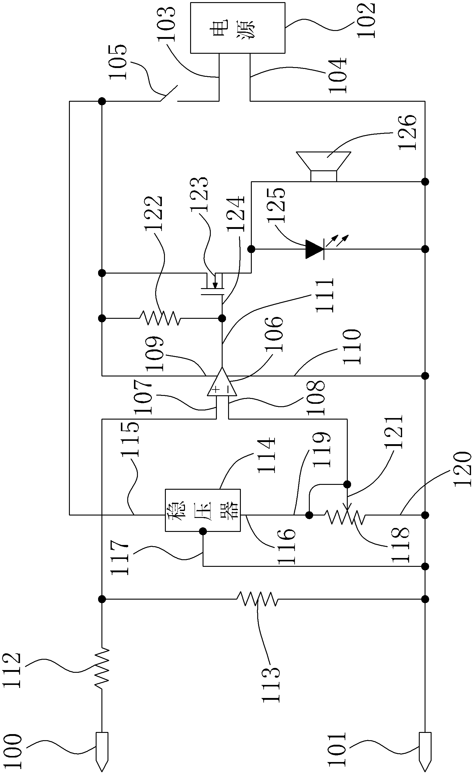
[0025] see figure 1 , figure 1 It is a circuit structure diagram of a preferred embodiment of the voltage detection circuit of the present invention.

[0026] In order to achieve the above object, the voltage detection circuit provided by the present invention includes:

[0027] The positive detection terminal 100 is used to connect with the positive terminal of the equipment to be tested;

[0028] The negative detection terminal 101 is used to connect with the negative terminal of the equipment to be tested;

[0029] A power supply 102, which has a positive pole 103 and a negative pole 104, the negative pole 104 is grounded, the voltage of the power supply 102 can be 5V, or other voltages or other voltages can be used after transformation;

[0030] A switch 105, which includes a near power supply terminal and a far power supply terminal, the near power supply terminal is connected to the positive pole 103 of the power supply 102;

[0031] A comparator 106, which includes ...


PUM


Abstract

The invention discloses a voltage detection circuit. The voltage detection circuit comprises a positive detection terminal, a negative detection terminal, a power supply, a switch, a comparator, a voltage stabilizer, a rheostat, a transistor and a display circuit, wherein the positive and negative detection terminals are connected with a positive terminal and a negative terminal of voltage to be detected; a near power supply terminal of the switch is connected with a positive electrode of the power supply; the comparator comprises a normal phase input terminal, an inverting input terminal, a power supply terminal, a grounding terminal and an output terminal; the power supply terminal of the comparator is connected with a far power supply terminal of the switch; the grounding terminal of the comparator is connected with a negative electrode of the power supply; a voltage-stabilizing input terminal of the voltage stabilizer is connected with the far power supply terminal of the switch; a voltage-stabilizing and grounding terminal of the voltage sterilizer is connected with the negative electrode of the power supply; a first fixing terminal of the rheostat is connected with a voltage-stabilizing outer terminal of the voltage stabilizer; a second fixing terminal is connected with the negative electrode of the power supply; a free terminal is connected with the inverting input terminal of the comparator; a grid electrode of the transistor is connected with the output terminal of the comparator; one of a source electrode and a drain electrode of the transistor is connected with the far power supply terminal of the switch; and the display circuit is connected with the other one of the source electrode and the drain electrode of the transistor.

Description

【Technical field】 [0001] The invention relates to a voltage detection circuit, in particular to a voltage detection circuit capable of detecting multiple voltage ranges. 【Background technique】 [0002] With the development and progress of science and technology, electronic products are more and more widely used in home and office occasions, and many electronic products will use power devices such as batteries or voltage adapters. [0003] For the above-mentioned power supply equipment, it is necessary to check whether the output voltage is normal before leaving the factory. The current detection method usually uses a multimeter for measurement. This method has a relatively low accuracy rate on the one hand and a slower speed on the other hand. [0004] In view of this, it is necessary to develop a voltage detection circuit to solve the above problems. 【Content of invention】 [0005] Therefore, the purpose of the present invention is to provide a voltage detection circuit ...

Claims


Application Information

Patent Timeline
IPC IPC(8): G01R19/165G01R15/00
Inventor 许京松
Owner SHENXUN COMP KUNSHAN
Why Eureka
Try Eureka