Loudspeaker box structure with loading hole
A loading hole and sound box technology, applied in the direction of the transducer shell/cabinet/bracket, frequency/direction characteristic device, sensor, etc., can solve the problems of frequency response attenuation, poor transient effect, limited improvement space, etc., and achieve cost reduction , the effect of reducing requirements
- Summary
- Abstract
- Description
- Claims
- Application Information
AI Technical Summary
Problems solved by technology
Method used
Image
Examples
Embodiment 1
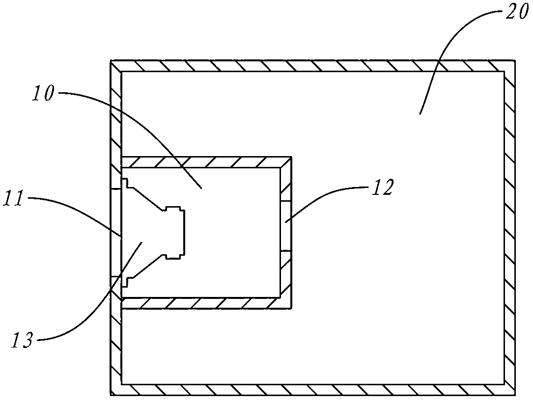
[0025] Such as figure 1 As shown, the first embodiment is in the form of a closed sound box. The driven cavity 20 occupies most of the space of the box body, and a sound cone hole 11 is arranged on the box body. At the position where the sound cone hole 11 is located, there is a smaller active cavity 10 and a loading hole 12 on the active cavity 10 in the box body. When the loudspeaker 13 is fixed to the cone hole 11 in a post-loaded manner, the active cavity 20 and the loudspeaker 13 form a sealed state, and the outer surface of the sound cone of the loudspeaker 13 communicates with the free space through the sound cone hole 11 . Simultaneously, the active cavity 10 communicates with the driven cavity 20 outside it only through the loading hole 12.
[0026] In this embodiment, the volume of the active chamber 10 is 1 / 3 of the volume of the driven chamber 20, and the cross-sectional area of the loading hole 12 is 2 / 3 of the cone area of the loudspeaker 13, compared to th...
Embodiment 2
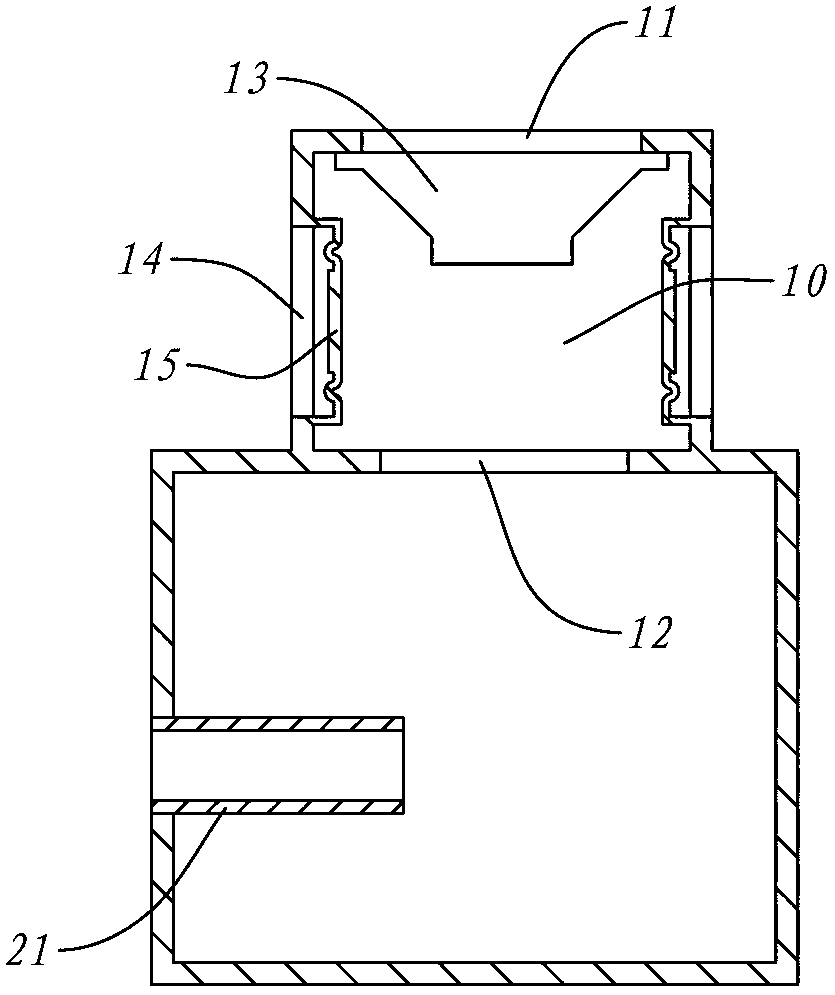
[0029] Such as figure 2 , the driven chamber 20 of this embodiment is an inverted phase, in that the driven chamber 20 communicates with the external active chamber 10 through the loading hole 12, and also has an inverter tube 21 which communicates with the external free space.
[0030] On the active cavity 10, there is a sound cone hole 11, and the loudspeaker 13 is fixed in the same way after loading. However, in addition to the cone of the speaker 13, the entire active cavity 10 also has two passive diaphragms 15 as vibration units. Each passive diaphragm 15 is fixed in the diaphragm hole 14 and keeps sealed with the active cavity. In this embodiment, the cross-sectional area of the loading hole 12 is 1 / 4 of the cross-sectional area of all the vibration units, that is, the cone of the speaker 13 and all the passive diaphragms 21 .
[0031] This embodiment is suitable for the design of the inverted cabinet. Compared with the first embodiment, the passive diaphragm 15 ...
Embodiment 3
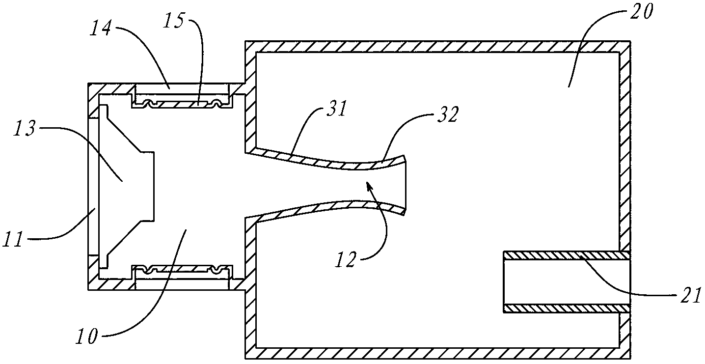
[0033] Such as image 3 , a sectional view of Embodiment 4 of the present invention. The active cavity 10 of the fourth embodiment is similar to the third embodiment, having a cone hole 11 and a rear-loaded speaker 13 , and a diaphragm hole 14 with a fixed diaphragm 15 . Simultaneously, the driven chamber 20 also has an inverter tube 21. The difference is that the loading hole 12 is no longer similar to the way in which the first and second embodiments are opened on a partition, but on the active chamber 10 there is a A buffer tube 31 is communicated, the inner wall of the buffer tube gradually shrinks from the active cavity 10 and extends into the passive cavity 20, while the inner wall of the end of the buffer tube 31 continues to extend and gradually expands to form a trumpet tube 32; the loading hole 12 is It is located at the smallest aperture where the trumpet tube 32 connects with the buffer tube 31. It can be seen that the active cavity 10 also includes the space in ...
PUM
 Abstract
Description
Claims
Application Information
 - R&D
- Intellectual Property
- Life Sciences
- Materials
- Tech Scout
- Unparalleled Data Quality
- Higher Quality Content
- 60% Fewer Hallucinations
Browse by: Latest US Patents, China's latest patents, Technical Efficacy Thesaurus, Application Domain, Technology Topic, Popular Technical Reports.
© 2025 PatSnap. All rights reserved.Legal|Privacy policy|Modern Slavery Act Transparency Statement|Sitemap|About US| Contact US: help@patsnap.com


