
Method and loom for producing woven fabrics having added weft effects

A technology of adding wefts and looms, applied to looms, textiles, embossing, etc., can solve problems such as hindering weft insertion

Inactive Publication Date: 2012-12-26
LINDAUER DORNIER GMBH
View PDF8 Cites 8 Cited by
  • Summary
  • Abstract
  • Description
  • Claims
  • Application Information

AI Technical Summary

Problems solved by technology

The disadvantage of this arrangement is that the weft insertion (Schusseintrag) is hindered by the curved bar in the area before the reed
The use of air looms in which the channel for guiding the weft thread to be picked is integrated into the reed is ruled out, and there are also limitations with this arrangement when using gripper elements

Method used


Image

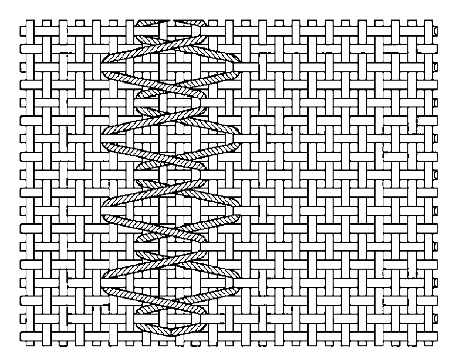
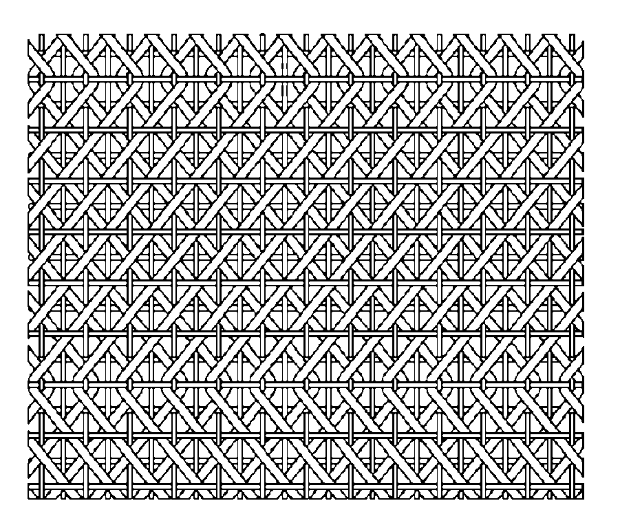
  • Method and loom for producing woven fabrics having added weft effects
  • Method and loom for producing woven fabrics having added weft effects
  • Method and loom for producing woven fabrics having added weft effects

Examples


Embodiment Construction

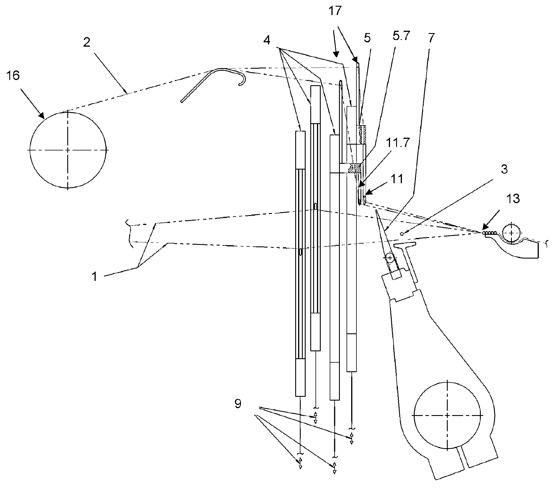
[0063] Figure 1a , b and 2 show in partial views a loom with a shedding drive 9 for driving the shedding element 4 through its vertical movement to form the sheds 1.1, 1.2 limited by the warp threads 1 . A shedding drive 9 known to the expert per se can consist, for example, of a set of rods and rods, which is arranged below the shedding element 4 and which transmits to the shedding element 4 the drive movement of a shedding machine, not shown, arranged outside the machine frame. However, any other electromechanical, hydraulic or pneumatic device can also be used as opening drive 9 .

[0064] The shedding element 4 is formed in the present example by a known heald frame with healds, through whose eyes the warp threads 1 are guided. Furthermore, there are also devices known to experts for picking the weft thread 3 in the weft thread direction 12 into the sheds 1.1, 1.2. This can be a device for mechanical weft insertion by means of a weaving shuttle or gripper or a device for...


PUM


Abstract

In a loom for producing woven fabrics (0) having added weft effects, an effect thread (2) fed in the warp direction above a weft thread (3) to be inserted is displaced in the weft direction (12) over a freely programmable displacement path (A) by means of a plurality of adjacent warp threads (1) drawn into different reed gaps (14). In order to interlace the effect thread (2) with the weft thread (3), the effect thread (2) is positioned beneath the weft thread (3) to be inserted and at the same time enters the open reed gaps (14) of a weaving reed device (10, 7, 7.1) that are upwardly open on one side. At the same time, a needle-shaped guide means (11) for the effect thread (2) is moved vertically and in the weft direction (12) in a plane that is located between the shedding elements (4) and the position of the weaving reed device (10, 7, 7.1) during weft insertion. The guide means (11) is displaced by an electromotive displacement drive (6) with respect to a shedding element (4), said drive driving the guide means (11) vertically.

Description

technical field [0001] The invention relates to a method and a weaving machine for producing a weft pattern with an additional weft pattern. Background technique [0002] It is known in the prior art for weaving machines to engage additional threads (which run in the warp direction) in weaving in such a way that a defined additional weft pattern is obtained. For this purpose, the fancy yarn is brought to another position in the direction of the weft thread prior to the picking of the weft thread for each movement cycle of the weaving machine. [0003] Such a weaving machine according to document EP 0 957 191 for example shows the device. The device is characterized in that there are means for moving the additional warp thread. The device is present in a curved bar, which is arranged on a load beam, which is arranged downstream of the reed. The disadvantage of this arrangement is that the weft insertion is hindered by the curved rod in the region before the reed. The use ...

Claims


Application Information

Patent Timeline
IPC IPC(8): D03C7/06D03D31/00
CPCD03C7/06D03D31/00D03C7/005D03C13/025
Inventor A.瓦豪德
Owner LINDAUER DORNIER GMBH
Learn More