
Stamping method and special mold for serialized porous and complex plug-in metal parts

A technology for inserting metal parts and metal parts, used in metal processing equipment, forming tools, manufacturing tools, etc., can solve the problem of poor consistency of the size and shape errors of the parts, affecting the accuracy of the parts and the life of the mold, quality and forming accuracy Difficult to guarantee and other problems, to achieve the effect of less stress concentration, less uneven deformation, and improved mold working conditions

Inactive Publication Date: 2016-06-08
南通集智知识产权服务有限公司
View PDF5 Cites 0 Cited by
  • Summary
  • Abstract
  • Description
  • Claims
  • Application Information

AI Technical Summary

Problems solved by technology

[0004] Purpose of the invention: The present invention provides a stamping method and a special die for serialized porous complex metal parts. The accuracy is difficult to guarantee, the process is long, the efficiency is low, the cost is high, and it is easy to cause stress concentration in some parts of the part, which will affect the precision of the part and the problem of low mold life.

Method used


Image

  • Stamping method and special mold for serialized porous and complex plug-in metal parts
  • Stamping method and special mold for serialized porous and complex plug-in metal parts
  • Stamping method and special mold for serialized porous and complex plug-in metal parts

Examples


specific Embodiment approach

[0034] Detailed ways: Below in conjunction with accompanying drawing, the present invention is further described:

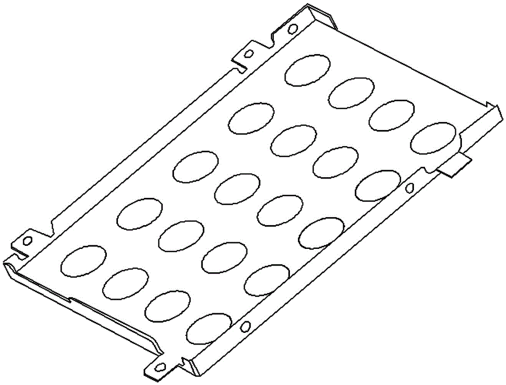
[0035] The invention provides a stamping method for serialized porous and complex plug-in metal parts, such as figure 2 As shown, combined with the process design plan and the shape and size requirements of the product, the layout process plan of the parts has been formulated. The process flow is: punching scattered holes and positioning holes ----- punching the remaining scattered holes and punching two arc-free The corresponding side of the square incision and the side with arc side notch--the opposite side of the curved two without arc-shaped notch---the opposite side of punching with arc-shaped notch--the arc-shaped notch after punching Bend the two sides and the opposite side ----- cut off the connecting part of the part and the strip.

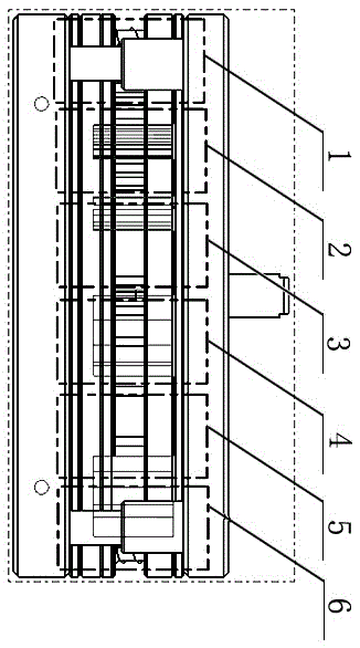
[0036] like image 3 Each of the shown stations is designed with an independent mold structure, and the mold includes...


PUM


Abstract

The invention provides a stamping method for serialized porous and complex metal parts, which is characterized in that: the specific steps of the method are as follows: (1), take the base material of the metal part, and then place the base material of the metal part in a first-stage punch to disperse Disperse punching and positioning holes are carried out under the punching die of the hole; (2), move the metal parts after the dispersed punching to the secondary punching and trimming die module, punch the remaining holes, and punch down at the same time Two groups of corresponding sides without arc-shaped cuts and cut sides with arc-shaped cuts in the strip feeding direction; (3) Bending the two symmetrical sides without arc-shaped cuts after punching; ( 4), punching the opposite side with arc-shaped incision; (5), bending the side with arc-shaped incision after punching and the side opposite to it; (6), cutting off the connecting part of the part and the strip; the present invention The adaptability of the mold is increased, thereby improving the production efficiency and prolonging the life of the mold.

Description

technical field [0001] The invention relates to the technical field of stamping dies for a series of porous and complex plug-in metal parts in electronic products, in particular to a high-precision modular progressive die integrating punching and bending. Background technique [0002] At present, for a class of serialized porous and complex plug-in metal parts in electronic products, three methods can be used traditionally: (1) Multiple sets of single-process dies punch out multiple holes, and then use a pair of single-process dies to shape the product. (2) According to the shape characteristics of the product, multiple sets of composite molds are used for step-by-step forming. (3) Using a multi-station progressive die, first punch out positioning holes and multiple holes, then partially blank, then form, and finally cut off to process the product. [0003] In the above (1) and (2) processes, the main disadvantages are: after the transfer of multiple molds, the consistency ...

Claims


Application Information

Patent Timeline
Patent Type & Authority Patents(China)
IPC IPC(8): B21D35/00B21D37/10
Inventor 王哲英马明旭王哲锋
Owner 南通集智知识产权服务有限公司
Learn More