Foreign material blowing structure on automatic soldering device

An automatic welding and driving structure technology, applied in auxiliary devices, welding equipment, metal processing equipment, etc., can solve the problems of low production efficiency, easy to stick foreign objects, time-consuming and labor-intensive problems, and achieve the goal of improving production efficiency and saving labor and time Effect

Active Publication Date: 2015-04-15
SUZHOU PIN SHINE TECH
View PDF7 Cites 0 Cited by
  • Summary
  • Abstract
  • Description
  • Claims
  • Application Information

AI Technical Summary

Problems solved by technology

[0002]In the existing soldering operation method, the product to be soldered has a socket, and the product has protruding solder to be soldered on the opposite outer sides on both sides of the socket. The contact pins are inserted into the jacks with a plugboard to support the product to be soldered, and the plugboard is turned over to realize that the soldering pins on both sides of the product are respectively inserted downwards into the flux tank and the molten tin furnace, and the contact pins are completed. Soldering, foreign matter is easy to stick to the soldering pin, so it is necessary to manually blow the soldering pin with an air gun to remove foreign matter and tin shavings. The operation of manually blowing foreign matter is time-consuming and laborious, and the production efficiency is low

Method used


Image

  • Foreign material blowing structure on automatic soldering device
  • Foreign material blowing structure on automatic soldering device
  • Foreign material blowing structure on automatic soldering device

Examples


Embodiment Construction

[0011] The present invention will be further described below in conjunction with the accompanying drawings.

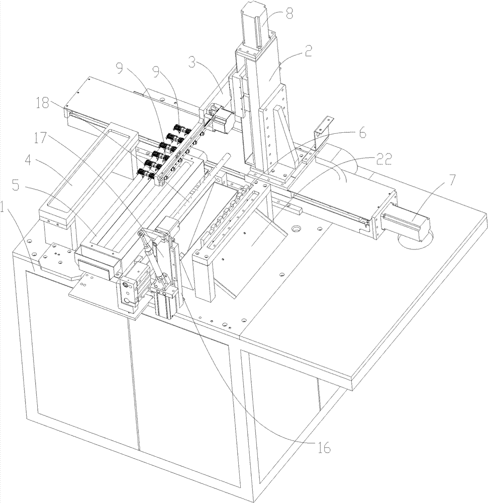
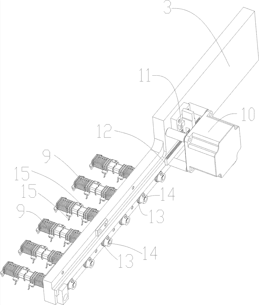
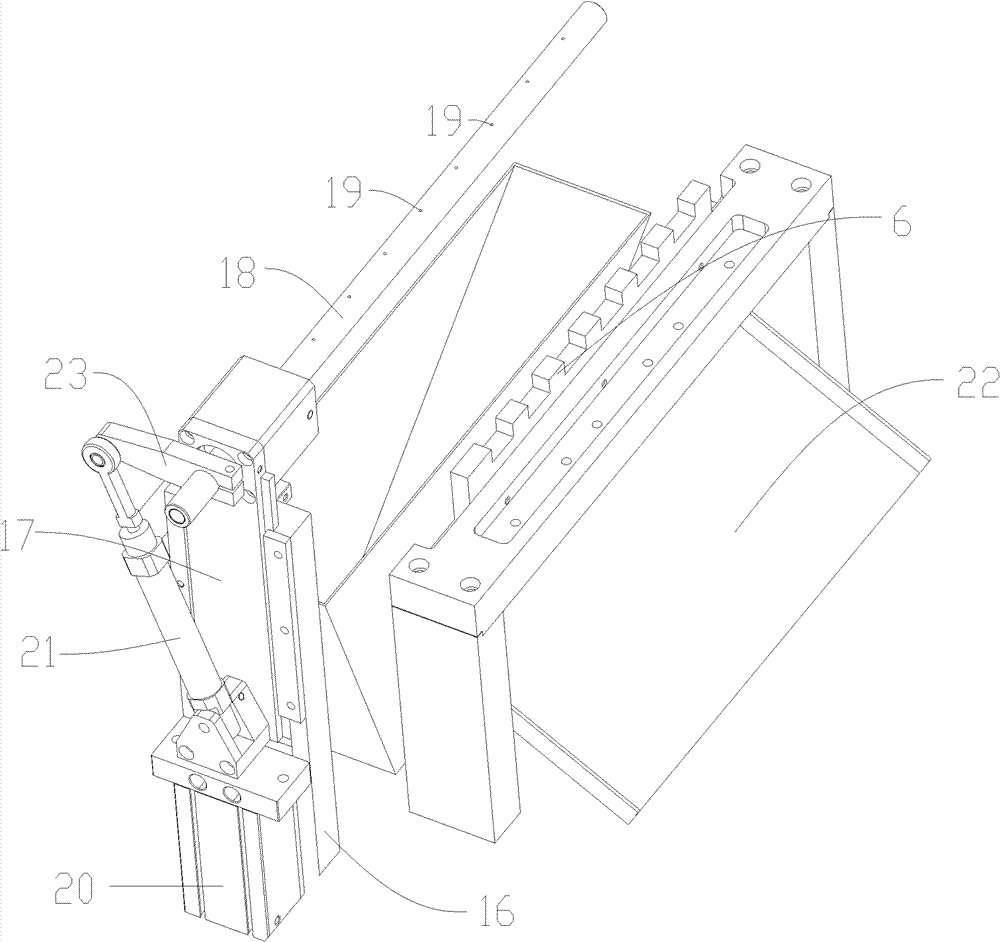
[0012] exist Figure 1-3 Among them, the product 9 to be soldered has a socket, and the product 9 has outwardly protruding soldering contacts 15 on the opposite outer sides of both sides of the socket. The connection base 2 on the support base 1, the mounting plate 3 that can be moved vertically on the connection base 2, can be rotated up and down on the mounting plate 3 and can be inserted into the socket of the product 9 to support The supporting board of the product, the first driving mechanism capable of driving the connecting seat 2 to move, the second driving mechanism capable of driving the mounting plate 3 to move, and the third driving mechanism capable of driving the supporting board to rotate are arranged on the supporting base 1 The flux tank 4 and the molten tin furnace 5 that can be inserted into the solder contact pin 15 of the product 9 and located...


PUM


Abstract

The invention discloses a foreign material blowing structure on an automatic soldering device. The foreign material blowing structure comprises a support base, a connection base, a first driving mechanism, a penetrating hole, an air blowing pipe, an air source and a second driving mechanism. The connection base can be movably arranged on the support base along a vertical direction, the first drive mechanism which can drive the connection base to move is arranged on the support base, the penetrating hole is opened on the connection base and extends along a horizontal direction, the ail blowing pipe can be rotatably penetrated into the penetrating hole, the air source is communicated with a pipe cavity of the air blowing pipe, the second driving mechanism which can drive the air blowing pipe to rotate is arranged on the connection base, and an air blowing hole communicated with the pipe cavity is opened on the pipe lateral wall of the air blowing pipe exposed out of the penetrating hole. When products are soldered and foreign materials are needed to be blown, air released by the air source enters the air blowing pipe and is blown out through the air blowing hole, a touch foot welded with tin on the product is blown, and foreign materials and tin chips are removed; the air blowing pipe is driven by the second driving mechanism to rotate, the air blowing hole moves in an arc to blow the whole surface of the touch foot, and as for different products, the heights of the touch feet can be different; and the first driving mechanism drives the connection base to move up and down, so that the air blowing hole is just aligned with the touch foot of the product, the blowing effect is guaranteed, the automatic foreign material blowing operation is labor saving and time saving, and the production efficiency is improved.

Description

technical field [0001] The invention relates to a foreign object blowing structure on an automatic soldering device. Background technique [0002] In the existing soldering operation method, the product to be soldered has a socket, and the product has protruding solder contacts on the opposite outer sides of the two sides of the socket, and inserts it into the socket with a plug board to support it. For soldering products, turn over the board to insert the soldering pins on both sides of the product downwards into the flux tank and tin liquid furnace respectively, and complete the soldering of the soldering pins. Foreign matter is easy to stick to the soldering pins, so manual work is required. Use an air gun to blow the soldering pins to remove foreign matter and tin shavings. The operation of manually blowing foreign matter is time-consuming and laborious, and the production efficiency is low. Contents of the invention [0003] The purpose of the present invention is to...

Claims


Application Information

Patent Timeline
Patent Type & Authority Patents(China)
IPC IPC(8): B23K3/08
Inventor 冯超
Owner SUZHOU PIN SHINE TECH
Why Eureka
Try Eureka