Self-excited pulse energy-saving valve

An energy-saving valve and pulse-type technology, applied in cleaning methods and appliances, chemical instruments and methods, and cleaning methods using gas flow, etc., can solve the problems of low pulse frequency, energy waste, unfavorable automatic production, etc., and achieve pulse frequency. The effect of adjusting and saving consumption

Active Publication Date: 2020-07-17
苏州众慧合智能制造有限公司
View PDF20 Cites 0 Cited by
  • Summary
  • Abstract
  • Description
  • Claims
  • Application Information

AI Technical Summary

Problems solved by technology

[0003] 1) Low pulse frequency;
[0004] 2) High labor intensity;
[0005] 3) Not conducive to automated production;
[0006] 4) There is a great waste of energy

Method used


Image

  • Self-excited pulse energy-saving valve

Examples


Embodiment

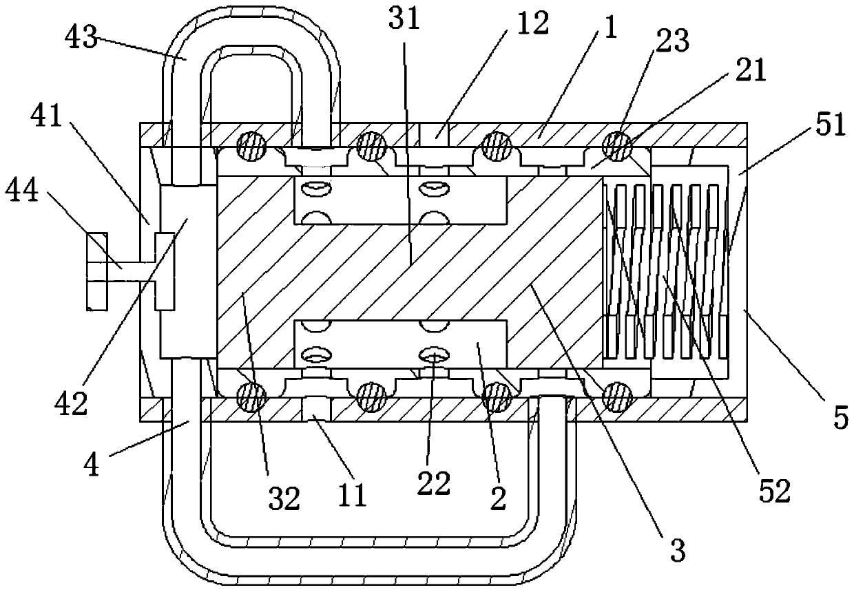
[0031] see figure 1 , this embodiment shows a self-excited pulse energy-saving valve:

[0032] It includes a housing 1 with an air inlet 11 and an air outlet 12 correspondingly opened on the upper end, a valve core sleeve 2 arranged in the housing 1 and used in conjunction with the air inlet 11 and the air outlet 12, and a spool set movably on the valve core The regulating valve core 3 in the sleeve 2, and the pulse regulating assembly 4 and the sealing pressure assembly 5 respectively arranged in the housing 1 at both ends of the regulating valve core 3;

[0033] The outer end of the spool cover 2 is provided with a number of connecting frustums 21, and the main body of the spool cover 2 between the two connecting truncated frustums 21 is provided with communicating air holes 22, and the joint between the connecting frustums 21 and the inner wall of the housing 1 is provided with Seals consisting of sealing rings;

[0034] In this embodiment, the number of connecting cones ...


PUM


Abstract

The invention discloses a self-excited pulse type energy saving valve which comprises a shell, a valve element sleeve, an adjusting valve element, a pulse adjusting assembly and a sealing pressure assembly. The upper end of the shell is provided with an air inlet and an air outlet correspondingly, the valve element sleeve is arranged in the shell and used in cooperation with the air inlet and theair outlet, the adjusting valve element is movably arranged in the valve element sleeve, the pulse adjusting assembly and the sealing pressure assembly are arranged in the portions, at the two ends ofthe adjusting valve element, in the shell, the outer end of the valve element sleeve is provided with a plurality of connection frustums, the portion, between every two adjacent connection frustums,of a valve element sleeve main body is provided with a vent hole, and the joints between the connection frustums and the inner wall of the shell are provided with sealing parts composed of sealing rings. A self-excited pulse type generation method is adopted, the blowing effect is ensured, meanwhile, compressed air consumption is saved by 30-50%, blown air pressure can be completely automaticallyadjusted, and meanwhile the pulse frequency is adjustable.

Description

technical field [0001] The invention relates to the field of industrial automation technology and energy-saving equipment, in particular to a self-excited pulse energy-saving valve. Background technique [0002] Many places in industrial production need to be purged with compressed air, and the amount of air used for purging is large, and the compressed air for normal purging is sprayed out at a certain pressure, so the purging effect is not ideal; in order to obtain a good purging effect, manual control The gas is switched on and off to achieve the effect of pulse, which has the following defects: [0003] 1) Low pulse frequency; [0004] 2) High labor intensity; [0005] 3) Not conducive to automated production; [0006] 4) There is a great waste of energy. [0007] Therefore, it is necessary to provide a self-excited pulse energy-saving valve to solve the above problems. Contents of the invention [0008] The purpose of the present invention is to provide a self-ex...

Claims


Application Information

Patent Timeline
Patent Type & Authority Patents(China)
IPC IPC(8): B05B1/00B05B1/08B05B1/30B08B5/02
CPCB05B1/005B05B1/08B05B1/3026B08B5/02
Inventor 张浩张万勇刘晓冬
Owner 苏州众慧合智能制造有限公司
Why Eureka
Try Eureka