

Stirring pin for surface stirring and rubbing
A technology of friction stirring and needle stirring, applied in non-electric welding equipment, welding equipment, metal processing equipment, etc., to achieve the effect of easy operation, excellent processing effect and simple structure
Inactive Publication Date: 2013-01-02
NANTONG TIANHUA HERUI TECH VENTURES
View PDF6 Cites 6 Cited by
- Summary
- Abstract
- Description
- Claims
- Application Information
AI Technical Summary
Problems solved by technology
Apparently, conventional friction stir welding / machining tools with pin designs are not suitable for surface modification by friction stir processing
Method used
View moreImage
Smart ImageViewing Examples

Examples
Embodiment 1
[0015] During processing, it is required to only cause material deformation within the range of 0.02-0.8 mm on the surface of the workpiece. Corresponding processing requirements: the rotation speed of the stirring needle is 200~800 rpm, and the horizontal running speed is 20~50 mm / min.
[0016] This embodiment has excellent processing effect, simple structure and easy operation.
Login to View More PUM
 Abstract
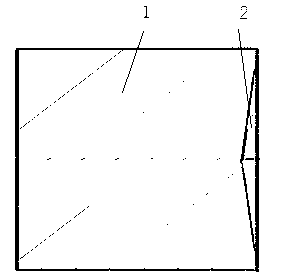
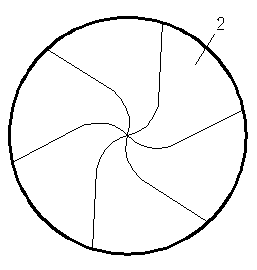
A stirring pin for surface stirring and rubbing is used in a machining process for surface stirring and rubbing. The stirring pin for surface stirring and rubbing is composed of a pin body (1) and a pin head (2), wherein the pin body (1) is in a cylindrical or conical structure, and the pin head (2) is arranged at one end of the pin body (1). The stirring pin is characterized in that the pin head (2) is in a concave structure with a high edge and a lower middle and provided with stripes diverging from inside to outside. During processing, material deformation of a workpiece surface is required to be in a range of 0.02mm to 0.8mm. Corresponding processing requirements include that the rotation speed of the stirring pin is 200 to 800 turns / minute, and the transverse operating speed is 20 to 50 millimeters / minute. The stirring pin for surface stirring and rubbing is good in processing effect, simple in structure and easy to operate.
Description
technical field [0001] The invention relates to a metal material processing method, and in particular provides a stirring pin for surface stirring and friction. Background technique [0002] Friction stir welding is a solid-state welding process with great application value. Its working principle is introduced as follows: a non-consumable welding tool consisting of a stirring needle and its base rotates at high speed to insert the stirring needle between the plates to be connected. When the shaft shoulder is in contact with the surface of the workpiece, the stirring needle moves laterally along the seam at the same time. The severe friction between the welding tool and the workpiece leads to a significant increase in the temperature of the welding zone, resulting in plasticization of the material. The role of the stirring pin is to stir the material in the weld area to make it produce plastic rheology and mixing, and the role of the shoulder is to apply forging to the mater...
Claims
Login to View More Application Information
Patent Timeline
 Patent Type & AuthorityApplications(China)
IPC IPC(8): B23K20/12
Inventor季历程
OwnerNANTONG TIANHUA HERUI TECH VENTURES