Mold locking device of hollow plastic product forming machine

A technology for a plastic product and a clamping device, which is applied in the field of clamping device of a hollow plastic product molding machine, can solve the problems of troublesome maintenance and replacement, affecting the clamping force, breaking away from the semicircular locking groove, etc., so as to save power consumption and simplify the structure. Effect

Active Publication Date: 2014-06-18
SUZHOU TONGDA MACHINERY
View PDF5 Cites 12 Cited by
  • Summary
  • Abstract
  • Description
  • Claims
  • Application Information

AI Technical Summary

Problems solved by technology

But this CN101890805B still has following shortcoming: the one, because the contact of the clamp block of a pair of clip electromagnetic valves of clamping block electromagnetic locking mechanism of clamping pin bar and the contact of clamping pin bar is shown as cohesive contact, so when the locking pin on the clamping pin bar When the joint neck corresponds to the semicircular locking groove of a pair of clamping blocks, the engagement effect on the clamping pin cannot be exerted, and even the clamping pin may break free from the semicircular locking groove during the inflation process of the inflation device , thus affecting the reliable closing effect of a pair of mold halves
Although this patent scheme is aware of this technical problem and expands the end of the locking pin with a diameter larger than the diameter of the locking neck, the locking pin flange is difficult to manufacture, and Even if the position is limited by the flange of the clamping pin rod, even a slight axial movement caused by the axial fit gap cannot be avoided; the second is due to the pair of clamping blocks used to hold or release the clamping pin rod 34 lacks a reasonable guide and limit, so there is a deflection situation, which affects the clamping force of a pair of clamps on the clamping pin; third, because the clamp spring is used, and the spring is easy to fatigue, so the durability of the clamp The force is difficult to guarantee; the fourth is that due to the use of magnetic clamping, and in order to ensure the locking force on the clamping pin, the clamping pin attracts the electromagnetic valve and the pair of clamping block electromagnetic valves must have strong electromagnetic suction. Thereby causing the waste of electric energy; the 5th, owing to the complex structure of clamping pin rod suction solenoid valve and a pair of clip block solenoid valves, high cost and difficult to guarantee working stability, it is easy to cause confusion in the actual use process, such as maintenance and replacement trouble

Method used


Image

  • Mold locking device of hollow plastic product forming machine
  • Mold locking device of hollow plastic product forming machine
  • Mold locking device of hollow plastic product forming machine

Examples


Embodiment

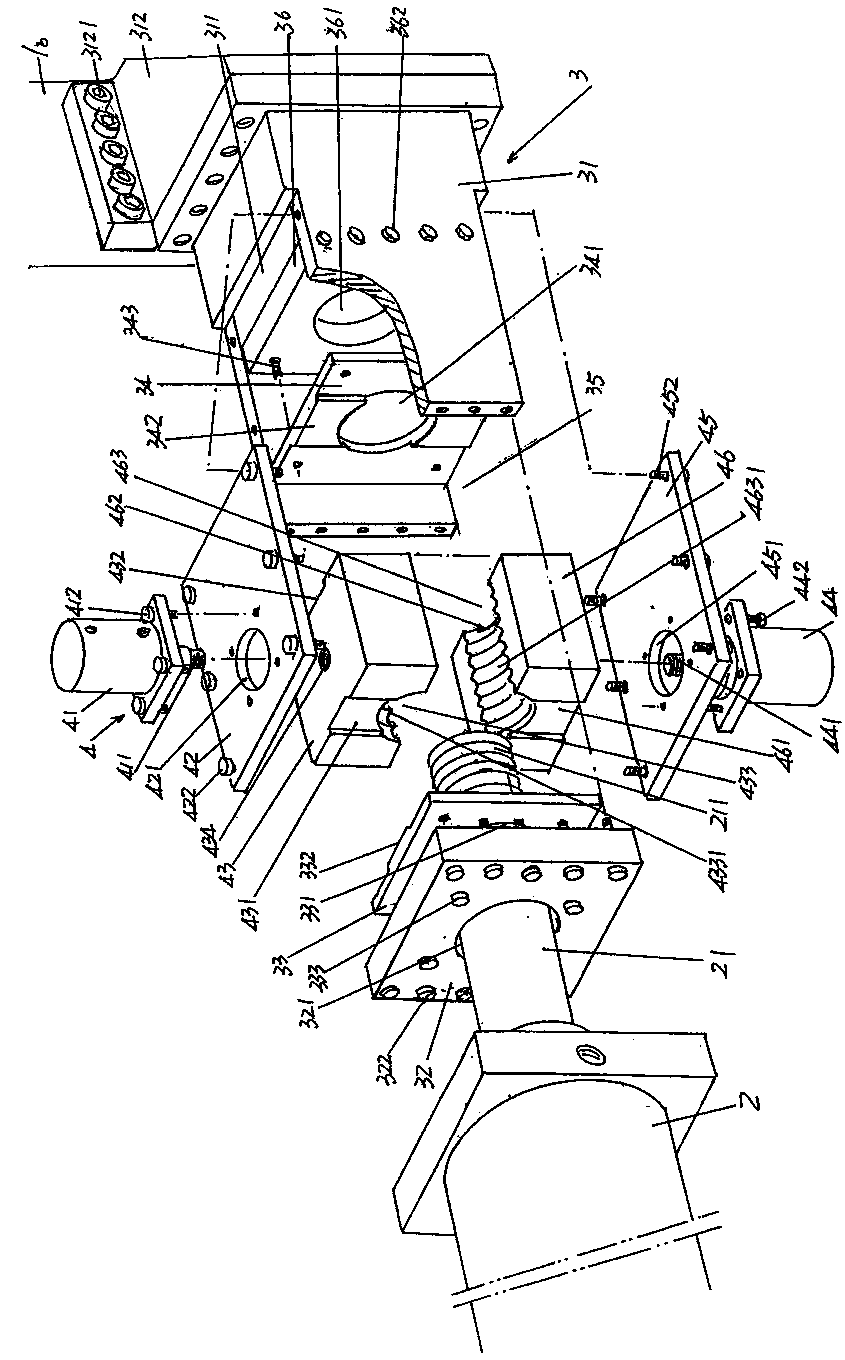
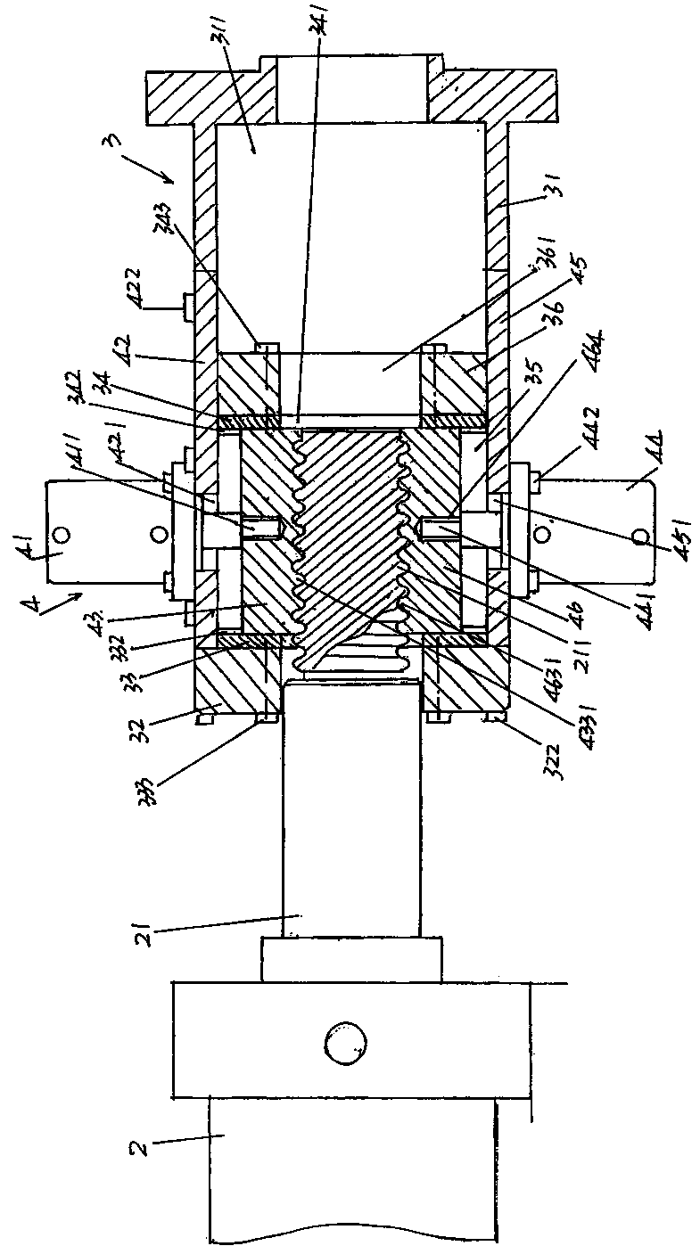
[0025] See figure 1 and figure 2 , what the applicant needs to explain is: in the following descriptions, all directional expressions such as left, right, up, and down are for the position status of the current illustration, so it cannot and should not be based on this. The technical solutions provided by the present invention constitute limitations.

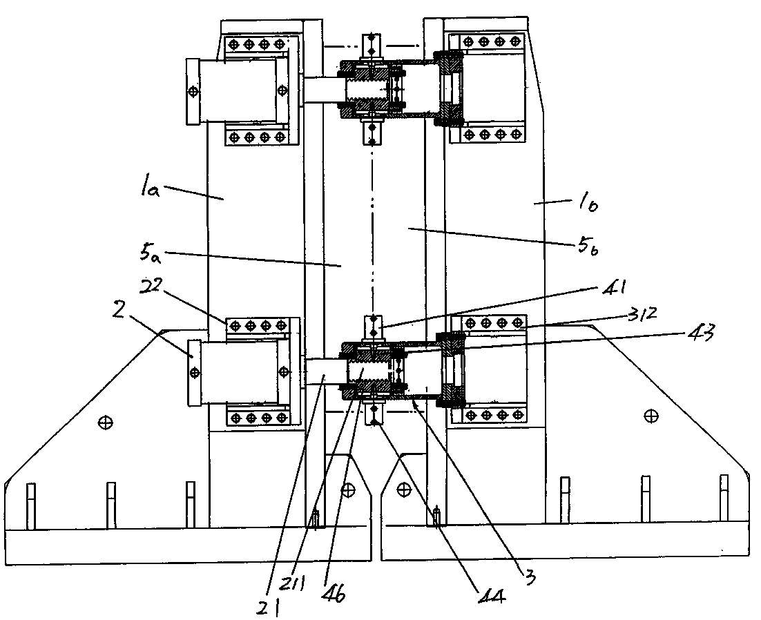
[0026] Since the clamping device mentioned in the present invention is applied to a molding machine for hollow plastic products, and according to known techniques, the molding machine for hollow plastic products has a left mold frame 1a ( image 3 shown) and right formwork 1b ( figure 1 and image 3 Shown), so the clamping device is set between the left and right mold bases 1a, 1b. Also, according to the known technology, for example, according to the teaching of paragraph 0025 of the description of CN101890805B mentioned by the applicant in the above background technology column, 4 or 6 identical structures can be...


PUM


Abstract

The invention relates to a mold locking device of a hollow plastic product forming machine, belonging to the field of a plastic product forming machine. The hollow plastic product forming machine comprises a left mold frame and a right mold frame, the mold locking device comprises a mold-locking actuating cylinder, a mold locking box and a mold-locking actuating cylinder grabbing mechanism, wherein the mold locking box comprises a mold locking box body, a cover plate, a first guide plate and a second guide plate; the mold-locking actuating cylinder grabbing mechanism comprises an upper actuating cylinder, an upper actuating cylinder seat plate, an upper engagement clamp block, a lower actuating cylinder, a lower actuating cylinder seat plate and a lower engagement clamp block; and the mold-locking actuating cylinder is horizontally arranged on the left mold frame, and cylinder column engagement teeth are formed at the surface of a mold-locking actuating cylinder column of the mold-locking actuating cylinder, at one end facing the mold locking box body. The mold locking device has the advantages that the closing effect of one pair of semi-molds can be ensured; the upper engagement clamp block and the lower engagement clamp block can be prevented from deflection to affect clamping forces on the mold-locking actuating cylinder column; the stability of vertical movement of the upper engagement clamp block and the lower engagement clamp block can be maintained in a long time; and the structure can be simplified, large locking forces for the mold-locking actuating cylinder column can be obtained with small mold locking forces, and electric energy can be saved.

Description

technical field [0001] The invention belongs to the technical field of plastic product forming machinery, and in particular relates to a mold clamping device of a hollow plastic product forming machine. Background technique [0002] As is well known in the industry, a hollow plastic product molding machine includes a machine base, a mold base moving device arranged on the machine base, and is connected to the mold base moving device and closed or mutually repelled under the work of the mold base moving device. The left and right mold bases and the clamping device installed between the left and right mold bases, one of the pair of half molds for blowing plastic products is installed on the left mold base, while the other half mold Installed on the right mold base, the left and right molds correspond to each other. When closing the mould, firstly the mold base moving device works to make the left and right mold bases close together, the left and right mold bases together with...

Claims


Application Information

Patent Timeline
Patent Type & Authority Patents(China)
IPC IPC(8): B29C49/56
Inventor 邱建成张礼华肖志林朱敏
Owner SUZHOU TONGDA MACHINERY
Why Eureka
Try Eureka