
Method of controlling the steering of a steerable portion of an aircraft undercarriage

A technology for aircraft landing gear and steering control, which is applied to landing gear, aircraft parts, chassis, etc., and can solve problems such as steering angle deviation

Active Publication Date: 2013-01-02
SAFRAN LANDING SYSTEMS
View PDF6 Cites 4 Cited by
  • Summary
  • Abstract
  • Description
  • Claims
  • Application Information

AI Technical Summary

Problems solved by technology

[0005] It has been found that in some cases, especially when making a sharp turn, or actually driving in a straight line while braking, or simply in cases where the aircraft is front-heavy, thereby creating high static forces on the landing gear In this case, the signal transmitted by the angular position sensor may deviate by a certain amount relative to the steering angle actually achieved by the steerable part of the landing gear

Method used


Image

  • Method of controlling the steering of a steerable portion of an aircraft undercarriage
  • Method of controlling the steering of a steerable portion of an aircraft undercarriage

Examples


Embodiment Construction

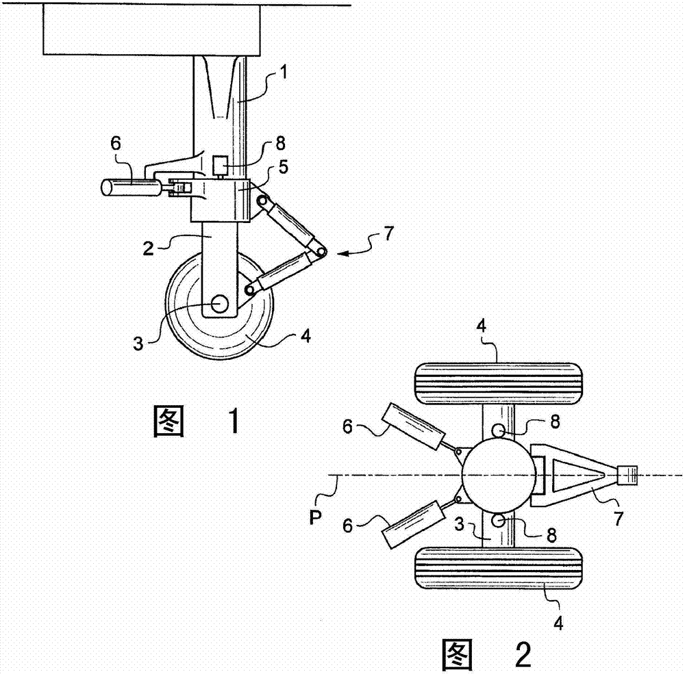
[0015] With reference to the accompanying drawings, the nose wheel landing gear of an aircraft generally comprises a strut 1 articulated to the structure of the aircraft. Bracket elements (not shown) extend between the aircraft structure and the strut to stabilize the strut 1 , and thus the undercarriage, in the shown deployed position.

[0016] The rod 2 slides inside the strut 1 and the bottom of the rod carries the shaft 3 receiving the wheel 4 . The collar 5 is mounted to turn on the bottom of the strut 1 so that it can be steered in a controlled manner by means of a diverter, which in this example consists of a push-pull mounted actuator 6 . The collar 5 and rod 2 are constrained to co-rotate by a scissor-like link 7 so that turning of the collar 5 turns the lever 2 and thus also the wheel 4 . An angular position sensor 8 is arranged on the strut to measure the angular position of the collar 5 and thus of the wheel 4 . The angular position sensor 8 transmits an angular ...


PUM


Abstract

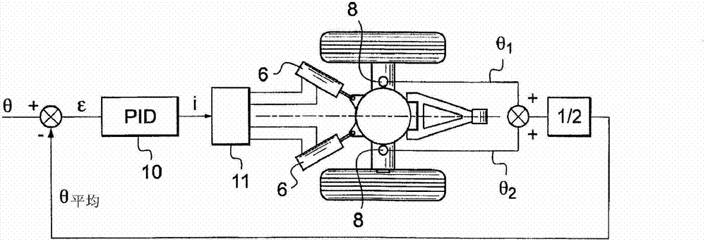
The invention relates to a method of controlling the steering of a steerable portion (2, 3, 4, 5) of an aircraft undercarriage that is fitted both with a steering member (6) for steering the steerable portion and also with at least two angular position sensors (8, 8) for sensing the angular position of the steerable portion in order to deliver respective signals representative of the angular position (Theta 1 and Theta 2) of the steerable portion, wherein the steering member is controlled by means of servo-control using information that is representative of the angular position of the steerable portion. According to the invention, the information representative of the angular position that is used is a mean (Theta mean) of the angular positions sensed by the at least two angular position sensors.

Description

technical field [0001] The invention relates to a steering control method of a steerable part of an aircraft landing gear. Background technique [0002] Certain undercarriages include steerable bottoms, this applies especially to nose wheel undercarriages, thereby enabling the aircraft to steer on the ground. For this purpose, the undercarriage is equipped with actuators (jack in push-pull configuration, rack meshing with a pinion) so that the steerable part can pivot in response to a steering command generated by means of, for example, a steering wheel in the cockpit . [0003] Feedback is provided by means of angular position sensors arranged on the undercarriage to measure the angular position of the steerable part and transmit an angular position signal which is used to form a feedback loop for servo control of the angular position. [0004] In a known manner, a double angular position sensor is provided by means of a second angular position sensor, so that two angular...

Claims


Application Information

Patent Timeline
IPC IPC(8): B64C25/50B64C25/24
CPCB64C25/50
Inventor M·本穆萨
Owner SAFRAN LANDING SYSTEMS
Learn More