Sample warper

A warping machine and fancy technology, applied in warping machines, textiles, papermaking, tool manufacturing, etc., can solve the problem that the silk thread can no longer place the warp rods correctly

Active Publication Date: 2013-01-02
KARL MAYER STOLL R&D GMBH
View PDF7 Cites 7 Cited by
  • Summary
  • Abstract
  • Description
  • Claims
  • Application Information

AI Technical Summary

Problems solved by technology

This can cause problems during restarting of the warping cylinders, si

Method used


Image

  • Sample warper

Examples


Embodiment Construction

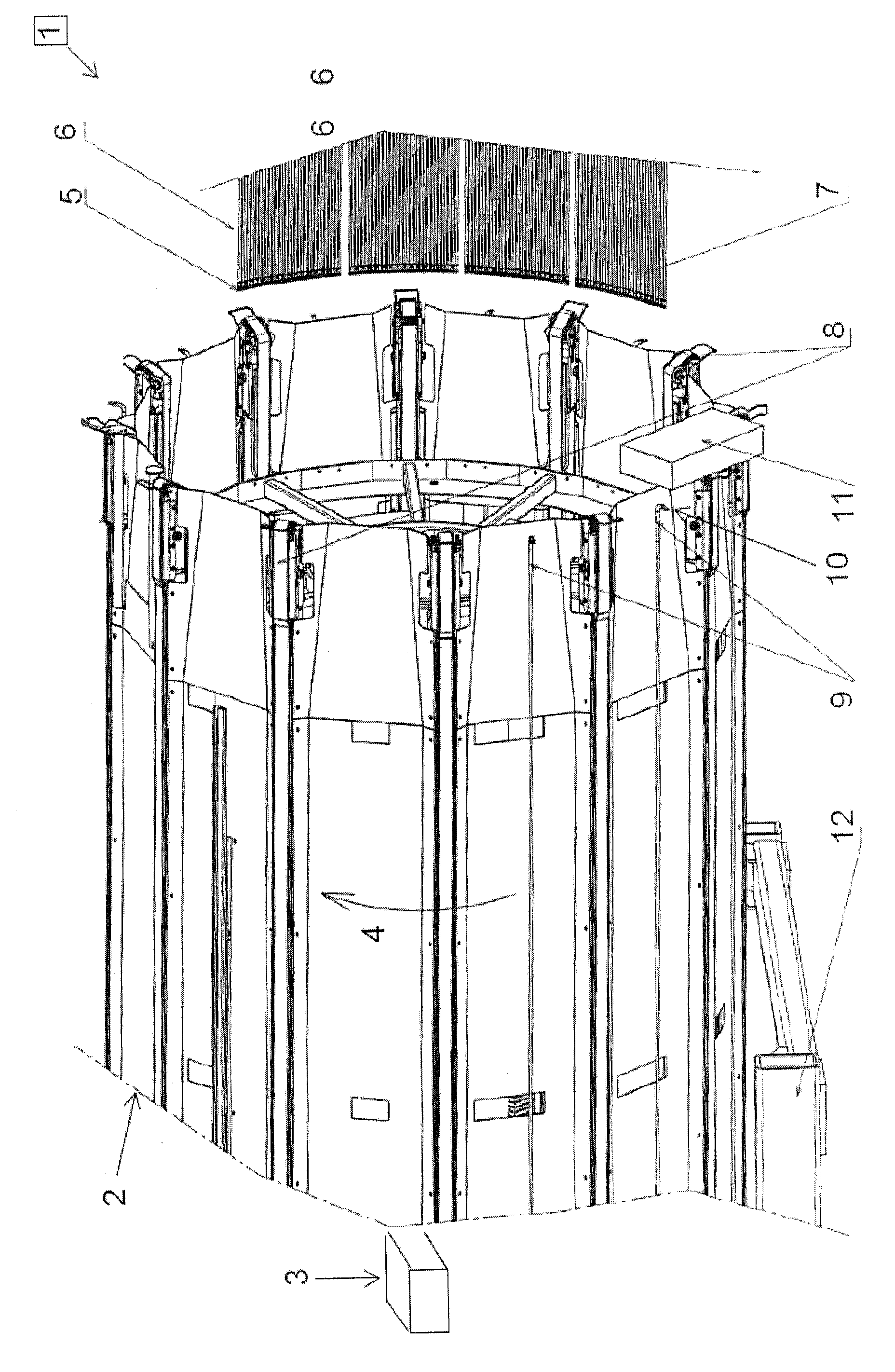
[0024] The effect warping machine 1 has a warping cylinder 2 connected to a schematically shown winding drive 3 . During winding, the winding drive 3 is able to turn the warping cylinder 2 in the direction indicated by the arrow 4 .

[0025] A number of bobbins are mounted on a creel (not shown). In this exemplary embodiment, up to 128 bobbins can be mounted on the creel.

[0026] The thread is drawn from each bobbin and guided through the thread guide eyelet 5 of the thread guide 6 . All yarn guides 6 together form an anti-lapping device 7 .

[0027] The yarn guide 6 can be moved in such a way that the yarn guide eyelet 5 is guided in the axial direction on the warping cylinder 2 . Therein, the thread guided through the thread guide eyelet 5 is then unwound on a conveyor belt 8 constituting the conveying surface, which moves parallel to the axis of said warping cylinder 2 away from the end at which an anti-lapping device 7 is mounted. If the thread is not unwound on the c...


PUM


Abstract

The sample warping machine (1) has a warping drum (2) that is connected with a winding drive (3). A yarn guide unit (6) is movably connected in parallel to the axis of the warping drum. Several attachment rods (9) are attached to the peripheral surface of the warping drum. A sensor arrangement (11) is arranged for detecting the positions of the attachment rods attached to the peripheral surface of the warping drum. The sensor arrangement is arranged opposite to the end surface of the warping drum.

Description

technical field [0001] The invention relates to a fancy warping machine with a warping cylinder connected to a winding drive, at least one thread guide movable parallel to the axis of the warping cylinder and a Multiple distribution sticks. Background technique [0002] This type of fancy warping machine is used to produce what is called a sample warp or short warp. For this, the warping cylinders are rotated. The yarn guides (generally, several at the same time) either guide the yarn around the circumference of the warping cylinder, where they are generally unwound on a conveyor belt, or guide the yarn at the front end of the warping cylinder , at this point, they are unwound on the "core", that is to say, on an auxiliary transport device, if it is not necessary to form the warp yarns of the sample. [0003] During the production of warp threads, that is to say during the production of sample warp threads, it is generally necessary to form what is known as a warp parting...

Claims


Application Information

Patent Timeline
IPC IPC(8): D02H3/00D02H13/02D02H9/00
CPCD02H3/00D02H3/04
Inventor M.富尔
Owner KARL MAYER STOLL R&D GMBH
Why Eureka
Try Eureka