Gas-liquid safety device on pump tank

A safety device, gas-liquid technology, applied in the fields of gas-liquid safety device, container safety device, and safety device, can solve the problems of inconvenient implementation, operation, maintenance and maintenance, poor overall system safety, and unstable pump pool liquid level, etc. To achieve the effect of unique and practical idea, stable and reliable effect, which is conducive to wide popularization and application

Active Publication Date: 2013-01-02
BEIJING TIANHAI IND
View PDF11 Cites 0 Cited by
  • Summary
  • Abstract
  • Description
  • Claims
  • Application Information

AI Technical Summary

Problems solved by technology

Its deficiencies, defects and disadvantages are: ①, the structure is not scientific and reasonable; ②, multi-holes are more destructive to the flange cover of the pump pool, which will inevitably lead to poor thermal insulation performance and heat leakage of the pump pool Larger, poor system stability, and certain potential safety hazards; ③, more gas discharge in the pump pool, larger return air volume, unstable liquid level in the pump pool, and poor overall system safety; ④, heat leakage It will cause the liquid level to be unstable, and at the same time cause the operation of the submersible pump to be unstable, and there are certain safety hazards; Difficulty, and there will be many safety hazards at the same time; ⑥, processing is relatively difficult, labor-intensive, time-consuming, and brings inconvenience to implementation, operation, repair and maintenance; ⑦, the overall appearance is not beautiful and generous

Method used


Image

  • Gas-liquid safety device on pump tank
  • Gas-liquid safety device on pump tank
  • Gas-liquid safety device on pump tank

Examples


Embodiment Construction

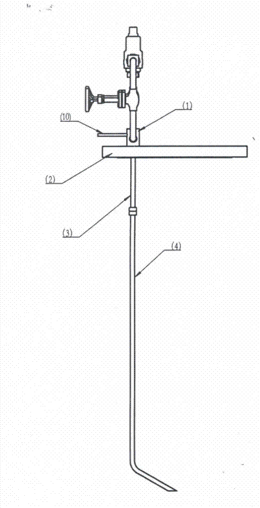
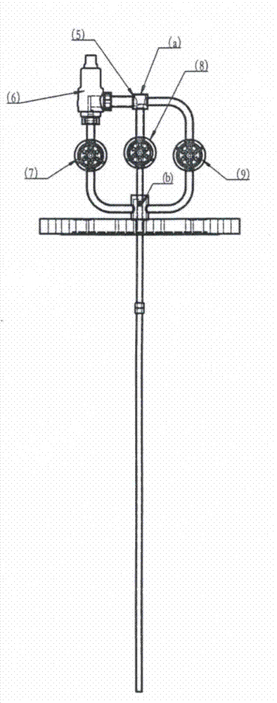
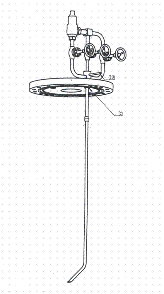
[0045] The present invention will be described in detail below in conjunction with the accompanying drawings. As attached to the manual figure 1 , 2 , as shown in 3:

[0046] A gas-liquid safety device on a pump pool, which consists of a gas-liquid casing valve seat 1, a pump pool flange cover 2, a liquid phase inner tube 3, an extension tube 4, a vent valve seat 5, a safety valve 6, a stop valve 7, and a residual Liquid discharge valve 8, manual gas phase vent valve 9, pressure introduction pipe 10, outlet a in vent valve seat 5, pressure introduction pipe interface b on gas-liquid casing valve seat 1, gas phase interface on pump pool flange cover 2 c composition;

[0047] For the gas-liquid safety device on the pump pool, the bottom end of the gas-liquid casing valve seat 1 is fixedly connected to the upper end of the gas phase interface c on the flange cover 2 of the pump pool, and its outlet a is placed in the vent valve seat 5 and the outlet a The upper end of the out...


PUM


Abstract

The invention discloses a gas-liquid safety device on a pump tank and belongs to the field of safety devices. The bottom end of a gas-liquid casing valve seat is fixed with the upper end of a gas-phase interface; an outlet is formed in an emptying valve seat, the upper end of the outlet is fixed with a round mouth at the upper end of the emptying valve seat, and the lower end of the outlet is fixed with the round mount at the lower end of the emptying valve seat. An extension pipe is fixed with the lower end of a liquid-phase inner pipe; the upper end of the liquid-phase inner pipe is fixed with the lower end of a raffinate discharging valve by a first connecting pipe; and the first connecting pipe is fixed with the upper end of the gas-liquid bushing valve seat. The upper end of the raffinate discharging valve is fixed with the lower end of the outlet by a second connecting pipe; a left pore of the gas-liquid casing valve seat is fixed with the lower end of a stop valve by a third connecting pipe; the upper end of the stop valve is fixed with the lower end of a safety valve by a fourth connecting pipe; a right pore of the gas-liquid casing valve seat is fixed with the lower end of a manual gas-phase emptying valve by a fifth connecting pipe; the upper end of the manual gas-phase emptying valve is fixed with the right pore of the emptying valve seat by a sixth connecting pipe; the left pore of the emptying valve seat is fixed with a side end of the safety valve by a seventh connecting pipe; and an interface of a duct is fixed with the duct. The gas-liquid safety device on the pump tank is used for ensuring the safety of the pump tank, and an intensive and combined structure is safe and reliable.

Description

technical field [0001] The gas-liquid safety device on the pump pool of the invention relates to the technical field of safety devices; in particular, it relates to the technical field of container safety devices; in particular, it relates to the technical field of gas-liquid safety devices on the pump pool. Background technique [0002] The so-called pump pool is a device that installs the cryogenic submersible pump in the pump pool tank filled with liquefied natural gas. Since the pump pool tank is filled with liquefied natural gas like a pool, the cryogenic submersible pump will be installed The pump pool tanks are collectively referred to as the pump pool; the pump pool is not only an image name, but also a uniform, dedicated and professional name used in this industry. The main purpose of the pump pool is: to input LNG to various vehicles using LNG, to input LNG loaded in the tanker to the LNG gas station, to input LNG into the tanker from the parent station (so as to ...

Claims


Application Information

Patent Timeline
Patent Type & Authority Applications(China)
IPC IPC(8): F04B49/10
Inventor 张增营刘占方吕兴民陈伟杨泽涛程金玉
Owner BEIJING TIANHAI IND
Why Eureka
Try Eureka